
Support
Microphone Wiring
| Brand | Model | Code | Connector | E6/B6/H6 | B3 | EMW | ISOMAX 2 |
|---|---|---|---|---|---|---|---|
| Anchor Audio | WB-6000 | AA | TA4F | Pin 1 = S Pin 2 = W 1k ohms 3 to 2 diagram | Pin 1 = S+B Pin 2 = R 1k ohms 3 to 2 diagram | Pin 1 = S Pin 2 = B Pin 3 = R 10k ohms 1 to 2 diagram | Pin 1 = S Pin 2 = B Pin 3 = R 10k ohms 1 to 2 Use W5 type headset diagram |
| Anchor Audio | WB-6400 | AA | TA4F | Pin 1 = S Pin 2 = W 1k ohms 3 to 2 diagram | Pin 1 = S+B Pin 2 = R 1k ohms 3 to 2 diagram | Pin 1 = S Pin 2 = B Pin 3 = R 10k ohms 1 to 2 diagram | Pin 1 = S Pin 2 = B Pin 3 = R 10k ohms 1 to 2 Use W5 type headset diagram |
| Anchor Audio | WB-8000 | AA | TA4F | Pin 1 = S Pin 2 = W 1k ohms 3 to 2 diagram | Pin 1 = S+B Pin 2 = R 1k ohms 3 to 2 diagram | Pin 1 = S Pin 2 = B Pin 3 = R 10k ohms 1 to 2 diagram | Pin 1 = S Pin 2 = B Pin 3 = R 10k ohms 1 to 2 Use W5 type headset diagram |
| Audix | B60 | AB | TA3F | Pin 1 = S Pin 3 = W 6.8k ohms 2 to 3 diagram | Pin 1 = S+B Pin 3 = R 6.8k ohms 2 to 3 diagram | Pin 1 = S Pin 2 = R Pin 3 = B 10k ohms 1 to 3 diagram | Pin 1 = S Pin 2 = R Pin 3 = B 10k ohms 1 to 3 Use W5 type headset diagram |
| Audix | RAD360-BP | AD | TA3F | Pin 1 = S Pin 2 = W 6.8k ohms 2 to 3 diagram | Pin 1 = S+B Pin 2 = R 6.8k ohms 2 to 3 diagram | Pin 1 = S Pin 2 = B Pin 3 = R 10k ohms 1 to 2 diagram | Pin 1 = S Pin 2 = B Pin 3 = R 10k ohms 1 to 2 Use W5 type headset diagram |
| AKG | PT300 | AG | AKG B-LOC (3.5mm locking male thread) | Sleeve = S Tip = W 10k ohms Tip to Sleeve diagram | Sleeve = S+B Tip = R diagram | Sleeve = S+B Tip = R diagram | Sleeve = S+B Tip = R Use W3 type headset diagram |
| AKG | PT500 | AG | AKG B-LOC (3.5mm locking male thread) | Sleeve = S Tip = W 10k ohms Tip to Sleeve diagram | Sleeve = S+B Tip = R diagram | Sleeve = S+B Tip = R diagram | Sleeve = S+B Tip = R Use W3 type headset diagram |
| AKG | PT51 | AG | AKG B-LOC (3.5mm locking male thread) | Sleeve = S Tip = W 10k ohms Tip to Sleeve diagram | Sleeve = S+B Tip = R diagram | Sleeve = S+B Tip = R diagram | Sleeve = S+B Tip = R Use W3 type headset diagram |
| AKG | DPT800 | AK | TA3F | Pin 1= S Pin 2 = W Jumper 2 to 3 1 to 3 = 6.8k ohms 200pF capacitor Pin 1 to Pin 2 diagram | Pin 1= S+B Pin 3 = R Jumper 2 to 3 diagram | Pin 1 = S+B Pin 3 = R Jumper 2 to 3 diagram | Pin 1 = S+B Pin 2 = R Jumper 2 to 3 Use W3 type headset diagram |
| AKG | DPT700 | AK | TA3F | Pin 1= S Pin 2 = W Jumper 2 to 3 1 to 3 = 6.8k ohms 200pF capacitor Pin 1 to Pin 2 diagram | Pin 1= S+B Pin 3 = R Jumper 2 to 3 diagram | Pin 1 = S+B Pin 3 = R Jumper 2 to 3 diagram | Pin 1 = S+B Pin 2 = R Jumper 2 to 3 Use W3 type headset diagram |
| AKG | PT2000 | AK | TA3F | Pin 1= S Pin 2 = W Jumper 2 to 3 1 to 3 = 6.8k ohms 200pF capacitor Pin 1 to Pin 2 diagram | Pin 1= S+B Pin 3 = R Jumper 2 to 3 diagram | Pin 1 = S+B Pin 3 = R Jumper 2 to 3 diagram | Pin 1 = S+B Pin 2 = R Jumper 2 to 3 Use W3 type headset diagram |
| AKG | PT40 | AK | TA3F | Pin 1= S Pin 2 = W Jumper 2 to 3 1 to 3 = 6.8k ohms 200pF capacitor Pin 1 to Pin 2 diagram | Pin 1= S+B Pin 3 = R Jumper 2 to 3 diagram | Pin 1 = S+B Pin 3 = R Jumper 2 to 3 diagram | Pin 1 = S+B Pin 2 = R Jumper 2 to 3 Use W3 type headset diagram |
| AKG | PT400 | AK | TA3F | Pin 1= S Pin 2 = W Jumper 2 to 3 1 to 3 = 6.8k ohms 200pF capacitor Pin 1 to Pin 2 diagram | Pin 1= S+B Pin 3 = R Jumper 2 to 3 diagram | Pin 1 = S+B Pin 3 = R Jumper 2 to 3 diagram | Pin 1 = S+B Pin 2 = R Jumper 2 to 3 Use W3 type headset diagram |
| AKG | PT4000 | AK | TA3F | Pin 1= S Pin 2 = W Jumper 2 to 3 1 to 3 = 6.8k ohms 200pF capacitor Pin 1 to Pin 2 diagram | Pin 1= S+B Pin 3 = R Jumper 2 to 3 diagram | Pin 1 = S+B Pin 3 = R Jumper 2 to 3 diagram | Pin 1 = S+B Pin 2 = R Jumper 2 to 3 Use W3 type headset diagram |
| AKG | PT45 | AK | TA3F | Pin 1= S Pin 2 = W Jumper 2 to 3 1 to 3 = 6.8k ohms 200pF capacitor Pin 1 to Pin 2 diagram | Pin 1= S+B Pin 3 = R Jumper 2 to 3 diagram | Pin 1 = S+B Pin 3 = R Jumper 2 to 3 diagram | Pin 1 = S+B Pin 2 = R Jumper 2 to 3 Use W3 type headset diagram |
| AKG | PT450 | AK | TA3F | Pin 1= S Pin 2 = W Jumper 2 to 3 1 to 3 = 6.8k ohms 200pF capacitor Pin 1 to Pin 2 diagram | Pin 1= S+B Pin 3 = R Jumper 2 to 3 diagram | Pin 1 = S+B Pin 3 = R Jumper 2 to 3 diagram | Pin 1 = S+B Pin 2 = R Jumper 2 to 3 Use W3 type headset diagram |
| AKG | PT4500 | AK | TA3F | Pin 1= S Pin 2 = W Jumper 2 to 3 1 to 3 = 6.8k ohms 200pF capacitor Pin 1 to Pin 2 diagram | Pin 1= S+B Pin 3 = R Jumper 2 to 3 diagram | Pin 1 = S+B Pin 3 = R Jumper 2 to 3 diagram | Pin 1 = S+B Pin 2 = R Jumper 2 to 3 Use W3 type headset diagram |
| AKG | PT470 | AK | TA3F | Pin 1= S Pin 2 = W Jumper 2 to 3 1 to 3 = 6.8k ohms 200pF capacitor Pin 1 to Pin 2 diagram | Pin 1= S+B Pin 3 = R Jumper 2 to 3 diagram | Pin 1 = S+B Pin 3 = R Jumper 2 to 3 diagram | Pin 1 = S+B Pin 2 = R Jumper 2 to 3 Use W3 type headset diagram |
| AKG | PT60 | AK | TA3F | Pin 1= S Pin 2 = W Jumper 2 to 3 1 to 3 = 6.8k ohms 200pF capacitor Pin 1 to Pin 2 diagram | Pin 1= S+B Pin 3 = R Jumper 2 to 3 diagram | Pin 1 = S+B Pin 3 = R Jumper 2 to 3 diagram | Pin 1 = S+B Pin 2 = R Jumper 2 to 3 Use W3 type headset diagram |
| AKG | PT61 | AK | TA3F | Pin 1= S Pin 2 = W Jumper 2 to 3 1 to 3 = 6.8k ohms 200pF capacitor Pin 1 to Pin 2 diagram | Pin 1= S+B Pin 3 = R Jumper 2 to 3 diagram | Pin 1 = S+B Pin 3 = R Jumper 2 to 3 diagram | Pin 1 = S+B Pin 2 = R Jumper 2 to 3 Use W3 type headset diagram |
| AKG | PT80 | AK | TA3F | Pin 1= S Pin 2 = W Jumper 2 to 3 1 to 3 = 6.8k ohms 200pF capacitor Pin 1 to Pin 2 diagram | Pin 1= S+B Pin 3 = R Jumper 2 to 3 diagram | Pin 1 = S+B Pin 3 = R Jumper 2 to 3 diagram | Pin 1 = S+B Pin 2 = R Jumper 2 to 3 Use W3 type headset diagram |
| AKG | PT81 | AK | TA3F | Pin 1= S Pin 2 = W Jumper 2 to 3 1 to 3 = 6.8k ohms 200pF capacitor Pin 1 to Pin 2 diagram | Pin 1= S+B Pin 3 = R Jumper 2 to 3 diagram | Pin 1 = S+B Pin 3 = R Jumper 2 to 3 diagram | Pin 1 = S+B Pin 2 = R Jumper 2 to 3 Use W3 type headset diagram |
| Audio Limited | RMS-2000-mxl | AL | Lemo 6-pin (FFA.2C.306) | Pin 1 = W Pin 5 = S Jumper 1 to 2 Jumper 3 to 4 diagram | Pin1 = R Pin5 = S + B Jumper 1 to 2 Jumper 3 to 4 diagram | Pin1 = B Pin 3 = R Pin 5 = S Jumper 1 to 6 Jumper 3 to 4 diagram | Pin 1 = B Pin 3 = R Pin 5 = S Jumper 1 to 6 Jumper 3 to 4 Use W5 type headset diagram |
| Audio Limited | TX2000 | AL | Lemo 6-pin (FFA.2C.306) | Pin 1 = W Pin 5 = S Jumper 1 to 2 Jumper 3 to 4 diagram | Pin1 = R Pin5 = S + B Jumper 1 to 2 Jumper 3 to 4 diagram | Pin1 = B Pin 3 = R Pin 5 = S Jumper 1 to 6 Jumper 3 to 4 diagram | Pin 1 = B Pin 3 = R Pin 5 = S Jumper 1 to 6 Jumper 3 to 4 Use W5 type headset diagram |
| Amplivox | S-1600T | AM | 3.5mm stereo non-locking plug | Sleeve = S Tip = W Jumper ring to tip diagram | Sleeve = S+B Tip = R Jumper ring to tip diagram | Sleeve = S+B Tip = R Jumper ring to tip diagram | Sleeve = S+B Tip = R Jumper ring to tip Use W3 type headset diagram |
| Amplivox | S-1690T | AM | 3.5mm stereo non-locking plug | Sleeve = S Tip = W Jumper ring to tip diagram | Sleeve = S+B Tip = R Jumper ring to tip diagram | Sleeve = S+B Tip = R Jumper ring to tip diagram | Sleeve = S+B Tip = R Jumper ring to tip Use W3 type headset diagram |
| Audio Technica | AEW-T1000 | AN | Hirose 4-pin HR10A-7P-4S | Jumper 1 to 2 Pin 1 = S Pin 3 = W 15k ohms 3 to 4 diagram | Jumper 1 to 2 Pin 1 = S + B Pin 3 = R 10k ohms 3 to 4 diagram | Jumper 1 to 2 Pin 1 = S Pin 3 = B Pin 4 = R diagram | Jumper 1 to 2 Pin 1 = S Pin 3 = B Pin 4 = R Use W5 type headset diagram |
| Audio Technica | AEW-T1000a | AN | Hirose 4-pin HR10A-7P-4S | Jumper 1 to 2 Pin 1 = S Pin 3 = W 15k ohms 3 to 4 diagram | Jumper 1 to 2 Pin 1 = S + B Pin 3 = R 10k ohms 3 to 4 diagram | Jumper 1 to 2 Pin 1 = S Pin 3 = B Pin 4 = R diagram | Jumper 1 to 2 Pin 1 = S Pin 3 = B Pin 4 = R Use W5 type headset diagram |
| Audio Technica | ATW-T1001 | AN | Hirose 4-pin HR10A-7P-4S | Jumper 1 to 2 Pin 1 = S Pin 3 = W 15k ohms 3 to 4 diagram | Jumper 1 to 2 Pin 1 = S + B Pin 3 = R 10k ohms 3 to 4 diagram | Jumper 1 to 2 Pin 1 = S Pin 3 = B Pin 4 = R diagram | Jumper 1 to 2 Pin 1 = S Pin 3 = B Pin 4 = R Use W5 type headset diagram |
| Audio Technica | ATW-T35 | AN | Hirose 4-pin HR10A-7P-4S | Jumper 1 to 2 Pin 1 = S Pin 3 = W 15k ohms 3 to 4 diagram | Jumper 1 to 2 Pin 1 = S + B Pin 3 = R 10k ohms 3 to 4 diagram | Jumper 1 to 2 Pin 1 = S Pin 3 = B Pin 4 = R diagram | Jumper 1 to 2 Pin 1 = S Pin 3 = B Pin 4 = R Use W5 type headset diagram |
| Audio Technica | ATW-T601 | AN | Hirose 4-pin HR10A-7P-4S | Jumper 1 to 2 Pin 1 = S Pin 3 = W 15k ohms 3 to 4 diagram | Jumper 1 to 2 Pin 1 = S + B Pin 3 = R 10k ohms 3 to 4 diagram | Jumper 1 to 2 Pin 1 = S Pin 3 = B Pin 4 = R diagram | Jumper 1 to 2 Pin 1 = S Pin 3 = B Pin 4 = R Use W5 type headset diagram |
| Audio Technica | ATW-T701 | AN | Hirose 4-pin HR10A-7P-4S | Jumper 1 to 2 Pin 1 = S Pin 3 = W 15k ohms 3 to 4 diagram | Jumper 1 to 2 Pin 1 = S + B Pin 3 = R 10k ohms 3 to 4 diagram | Jumper 1 to 2 Pin 1 = S Pin 3 = B Pin 4 = R diagram | Jumper 1 to 2 Pin 1 = S Pin 3 = B Pin 4 = R Use W5 type headset diagram |
| Audio Technica | ATW-T75 | AN | Hirose 4-pin HR10A-7P-4S | Jumper 1 to 2 Pin 1 = S Pin 3 = W 15k ohms 3 to 4 diagram | Jumper 1 to 2 Pin 1 = S + B Pin 3 = R 10k ohms 3 to 4 diagram | Jumper 1 to 2 Pin 1 = S Pin 3 = B Pin 4 = R diagram | Jumper 1 to 2 Pin 1 = S Pin 3 = B Pin 4 = R Use W5 type headset diagram |
| Audio Technica | ESW-T211 | AN | Hirose 4-pin HR10A-7P-4S | Jumper 1 to 2 Pin 1 = S Pin 3 = W 15k ohms 3 to 4 diagram | Jumper 1 to 2 Pin 1 = S + B Pin 3 = R 10k ohms 3 to 4 diagram | Jumper 1 to 2 Pin 1 = S Pin 3 = B Pin 4 = R diagram | Jumper 1 to 2 Pin 1 = S Pin 3 = B Pin 4 = R Use W5 type headset diagram |
| Audio Technica | ATW-T5201 | ANCH | Hirose 4 pin screw-down cH-style | Jumper 1 to 2 Pin 1 = S Pin 3 = W 15k ohms 3 to 4 diagram | Jumper 1 to 2 Pin 1 = S + B Pin 3 = R 10k ohms 3 to 4 diagram | Jumper 1 to 2 Pin 1 = S Pin 3 = B Pin 4 = R diagram | Jumper 1 to 2 Pin 1 = S Pin 3 = B Pin 4 = R Use W5 type headset diagram |
| Samson | Airline AL1 | AS | 2.5mm Stereo | Sleeve = S Tip = W Jumper ring to tip diagram | Tip = R Jumper Ring to Tip Sleeve = S+B diagram | Tip = R Jumper Ring to Tip Sleeve = S+B diagram | - |
| Audio Technica | ATW-T1801 | AT | Hirose 4-pin HR10A-7P-4S | Pin 1 = S Pin 3 = W Jumper 1 to 2 2.7k ohms 3 to 4 diagram | Pin 1 = S Pin 3 = B Pin 4 = R Jumper 1 to 2 diagram | Pin 1 = S Pin 3 = B Pin 4 = R Jumper 1 to 2 diagram | Pin 1 = S Pin 3 = B Pin 4 = R Jumper 1 to 2 Use W5 type headset diagram |
| Audio Technica | ATW-T201 | AT | Hirose 4-pin HR10A-7P-4S | Pin 1 = S Pin 3 = W Jumper 1 to 2 2.7k ohms 3 to 4 diagram | Pin 1 = S Pin 3 = B Pin 4 = R Jumper 1 to 2 diagram | Pin 1 = S Pin 3 = B Pin 4 = R Jumper 1 to 2 diagram | Pin 1 = S Pin 3 = B Pin 4 = R Jumper 1 to 2 Use W5 type headset diagram |
| Audio Technica | ATW-T210 | AT | Hirose 4-pin HR10A-7P-4S | Pin 1 = S Pin 3 = W Jumper 1 to 2 2.7k ohms 3 to 4 diagram | Pin 1 = S Pin 3 = B Pin 4 = R Jumper 1 to 2 diagram | Pin 1 = S Pin 3 = B Pin 4 = R Jumper 1 to 2 diagram | Pin 1 = S Pin 3 = B Pin 4 = R Jumper 1 to 2 Use W5 type headset diagram |
| Audio Technica | ATW-T210a | AT | Hirose 4-pin HR10A-7P-4S | Pin 1 = S Pin 3 = W Jumper 1 to 2 2.7k ohms 3 to 4 diagram | Pin 1 = S Pin 3 = B Pin 4 = R Jumper 1 to 2 diagram | Pin 1 = S Pin 3 = B Pin 4 = R Jumper 1 to 2 diagram | Pin 1 = S Pin 3 = B Pin 4 = R Jumper 1 to 2 Use W5 type headset diagram |
| Audio Technica | ATW-T27 | AT | Hirose 4-pin HR10A-7P-4S | Pin 1 = S Pin 3 = W Jumper 1 to 2 2.7k ohms 3 to 4 diagram | Pin 1 = S Pin 3 = B Pin 4 = R Jumper 1 to 2 diagram | Pin 1 = S Pin 3 = B Pin 4 = R Jumper 1 to 2 diagram | Pin 1 = S Pin 3 = B Pin 4 = R Jumper 1 to 2 Use W5 type headset diagram |
| Audio Technica | ATW-T31 | AT | Hirose 4-pin HR10A-7P-4S | Pin 1 = S Pin 3 = W Jumper 1 to 2 2.7k ohms 3 to 4 diagram | Pin 1 = S Pin 3 = B Pin 4 = R Jumper 1 to 2 diagram | Pin 1 = S Pin 3 = B Pin 4 = R Jumper 1 to 2 diagram | Pin 1 = S Pin 3 = B Pin 4 = R Jumper 1 to 2 Use W5 type headset diagram |
| Audio Technica | ATW-T310 | AT | Hirose 4-pin HR10A-7P-4S | Pin 1 = S Pin 3 = W Jumper 1 to 2 2.7k ohms 3 to 4 diagram | Pin 1 = S Pin 3 = B Pin 4 = R Jumper 1 to 2 diagram | Pin 1 = S Pin 3 = B Pin 4 = R Jumper 1 to 2 diagram | Pin 1 = S Pin 3 = B Pin 4 = R Jumper 1 to 2 Use W5 type headset diagram |
| Audio Technica | ATW-T310b | AT | Hirose 4-pin HR10A-7P-4S | Pin 1 = S Pin 3 = W Jumper 1 to 2 2.7k ohms 3 to 4 diagram | Pin 1 = S Pin 3 = B Pin 4 = R Jumper 1 to 2 diagram | Pin 1 = S Pin 3 = B Pin 4 = R Jumper 1 to 2 diagram | Pin 1 = S Pin 3 = B Pin 4 = R Jumper 1 to 2 Use W5 type headset diagram |
| Audio Technica | ATW-T51 | AT | Hirose 4-pin HR10A-7P-4S | Pin 1 = S Pin 3 = W Jumper 1 to 2 2.7k ohms 3 to 4 diagram | Pin 1 = S Pin 3 = B Pin 4 = R Jumper 1 to 2 diagram | Pin 1 = S Pin 3 = B Pin 4 = R Jumper 1 to 2 diagram | Pin 1 = S Pin 3 = B Pin 4 = R Jumper 1 to 2 Use W5 type headset diagram |
| Audio Technica | ATW-3201 | ATCH | Hirose 4 pin screw-down cH-style | Pin 1 = S Pin 3 = W Jumper 1 to 2 2.7k ohms 3 to 4 diagram | Pin 1 = S Pin 3 = B Pin 4 = R Jumper 1 to 2 diagram | Pin 1 = S Pin 3 = B Pin 4 = R Jumper 1 to 2 diagram | Pin 1 = S Pin 3 = B Pin 4 = R Jumper 1 to 2 Use W5 type headset diagram |
| Audio Technica | ATW-T101 | AW | TA5F | Pin 1 = S Pin 3 = W Jumper 2 to 4 4.7k ohms 1 to 3 diagram | Pin 1 = S + B Pin 3 = R Jumper 2 to 4 diagram | Pin 1 = S + B Pin 3 = R Jumper 2 to 4 diagram | Pin 1 = S Pin 3 = B Pin 2 = R Jumper 1 to 4 Use W5 type headset diagram |
| Shure | AD1 | AX | TA4F | Pin1 = S Pin3 = W 4.7k pin 2 to Pin 3 Crimp fingers to shielddiagram | Pin1 = S+B Pin3 = R 10k ohms 2 to 3 Crimp fingers to shielddiagram | Pin1 = Shield Pin2 = R Pin3 = B 22k pin1 to pin 3 Crimp fingers to shielddiagram | Pin1 = Shield Pin2 = R Pin3 = B 22k pin 1 to pin 3 Crimp fingers to shieldUse W5 type headset diagram |
| Shure | ADX1 | AX | TA4F | Pin1 = S Pin3 = W 4.7k pin 2 to Pin 3 Crimp fingers to shielddiagram | Pin1 = S+B Pin3 = R 10k ohms 2 to 3 Crimp fingers to shielddiagram | Pin1 = Shield Pin2 = R Pin3 = B 22k pin1 to pin 3 Crimp fingers to shielddiagram | Pin1 = Shield Pin2 = R Pin3 = B 22k pin 1 to pin 3 Crimp fingers to shieldUse W5 type headset diagram |
| Shure | AXT100TA4F | AX | TA4F | Pin1 = S Pin3 = W 4.7k pin 2 to Pin 3 Crimp fingers to shielddiagram | Pin1 = S+B Pin3 = R 10k ohms 2 to 3 Crimp fingers to shielddiagram | Pin1 = Shield Pin2 = R Pin3 = B 22k pin1 to pin 3 Crimp fingers to shielddiagram | Pin1 = Shield Pin2 = R Pin3 = B 22k pin 1 to pin 3 Crimp fingers to shieldUse W5 type headset diagram |
| Shure | GLXD1 | AX | TA4F | Pin1 = S Pin3 = W 4.7k pin 2 to Pin 3 Crimp fingers to shielddiagram | Pin1 = S+B Pin3 = R 10k ohms 2 to 3 Crimp fingers to shielddiagram | Pin1 = Shield Pin2 = R Pin3 = B 22k pin1 to pin 3 Crimp fingers to shielddiagram | Pin1 = Shield Pin2 = R Pin3 = B 22k pin 1 to pin 3 Crimp fingers to shieldUse W5 type headset diagram |
| Shure | PGXD1 | AX | TA4F | Pin1 = S Pin3 = W 4.7k pin 2 to Pin 3 Crimp fingers to shielddiagram | Pin1 = S+B Pin3 = R 10k ohms 2 to 3 Crimp fingers to shielddiagram | Pin1 = Shield Pin2 = R Pin3 = B 22k pin1 to pin 3 Crimp fingers to shielddiagram | Pin1 = Shield Pin2 = R Pin3 = B 22k pin 1 to pin 3 Crimp fingers to shieldUse W5 type headset diagram |
| Shure | QLXD1 | AX | TA4F | Pin1 = S Pin3 = W 4.7k pin 2 to Pin 3 Crimp fingers to shielddiagram | Pin1 = S+B Pin3 = R 10k ohms 2 to 3 Crimp fingers to shielddiagram | Pin1 = Shield Pin2 = R Pin3 = B 22k pin1 to pin 3 Crimp fingers to shielddiagram | Pin1 = Shield Pin2 = R Pin3 = B 22k pin 1 to pin 3 Crimp fingers to shieldUse W5 type headset diagram |
| Shure | ULXD1 | AX | TA4F | Pin1 = S Pin3 = W 4.7k pin 2 to Pin 3 Crimp fingers to shielddiagram | Pin1 = S+B Pin3 = R 10k ohms 2 to 3 Crimp fingers to shielddiagram | Pin1 = Shield Pin2 = R Pin3 = B 22k pin1 to pin 3 Crimp fingers to shielddiagram | Pin1 = Shield Pin2 = R Pin3 = B 22k pin 1 to pin 3 Crimp fingers to shieldUse W5 type headset diagram |
| Azden | 15BT | AZ | 3.5mm stereo locking plug | Sleeve = S Tip = w 3k ohms T to S diagram | Tip = R Sleeve = S+B diagram | Tip = R Sleeve = S+B diagram | Tip = R Sleeve = S+B diagram |
| Azden | 35BT | AZ | 3.5mm stereo locking plug | Sleeve = S Tip = w 3k ohms T to S diagram | Tip = R Sleeve = S+B diagram | Tip = R Sleeve = S+B diagram | Tip = R Sleeve = S+B diagram |
| Beyerdynamic | TS-170 | BS | Lemo 4-pin FG331 | Pin 2 = S Pin 1 = W 10k ohms 1 to 3 diagram | Pin 2 = S + B Pin 4 = R diagram | Pin 1 = B Pin 2 = S Pin 3 = R diagram | Pin 1 = B Pin 2 = S Pin 3 = R use w5 type headset diagram |
| Beyerdynamic | TS-170p | BS | Lemo 4-pin FG331 | Pin 2 = S Pin 1 = W 10k ohms 1 to 3 diagram | Pin 2 = S + B Pin 4 = R diagram | Pin 1 = B Pin 2 = S Pin 3 = R diagram | Pin 1 = B Pin 2 = S Pin 3 = R use w5 type headset diagram |
| Beyerdynamic | TS-190 (VHF) | BS | Lemo 4-pin FG331 | Pin 2 = S Pin 1 = W 10k ohms 1 to 3 diagram | Pin 2 = S + B Pin 4 = R diagram | Pin 1 = B Pin 2 = S Pin 3 = R diagram | Pin 1 = B Pin 2 = S Pin 3 = R use w5 type headset diagram |
| Beyerdynamic | TSP | BS | Lemo 4-pin FG331 | Pin 2 = S Pin 1 = W 10k ohms 1 to 3 diagram | Pin 2 = S + B Pin 4 = R diagram | Pin 1 = B Pin 2 = S Pin 3 = R diagram | Pin 1 = B Pin 2 = S Pin 3 = R use w5 type headset diagram |
| Beyerdynamic | TS 316 | BT | Lemo 4-pin FG331 | Pin 1 = S Pin 4 = W 10k ohms 2 to 4 diagram | Pin 1 = S+B Pin 3 = R diagram | Pin 1 = S Pin 2 = R Pin 4 = B 10k ohms 1 to 4 diagram | Pin 1 = S Pin 2 = R Pin 4 = B 10k ohms 1 to 4 Use W5 type headset diagram |
| Beyerdynamic | TS 400 | BT | Lemo 4-pin FG331 | Pin 1 = S Pin 4 = W 10k ohms 2 to 4 diagram | Pin 1 = S+B Pin 3 = R diagram | Pin 1 = S Pin 2 = R Pin 4 = B 10k ohms 1 to 4 diagram | Pin 1 = S Pin 2 = R Pin 4 = B 10k ohms 1 to 4 Use W5 type headset diagram |
| Beyerdynamic | TS 600 | BT | Lemo 4-pin FG331 | Pin 1 = S Pin 4 = W 10k ohms 2 to 4 diagram | Pin 1 = S+B Pin 3 = R diagram | Pin 1 = S Pin 2 = R Pin 4 = B 10k ohms 1 to 4 diagram | Pin 1 = S Pin 2 = R Pin 4 = B 10k ohms 1 to 4 Use W5 type headset diagram |
| Comtek | M-216 | C2 | 2.5mm locking mono | Sleeve = S Tip = W diagram | Sleeve = B+S Tip = R diagram | Sleeve = B+S Tip = R diagram | Sleeve = B+S Tip = R Use W3 Type Headset diagram |
| Comtek | M-72 (Switchcraft 851 connector) | C2 | 2.5mm locking mono | Sleeve = S Tip = W diagram | Sleeve = B+S Tip = R diagram | Sleeve = B+S Tip = R diagram | Sleeve = B+S Tip = R Use W3 Type Headset diagram |
| Comtek | M-72 (3.5mm non-locking connector) | C3 | 3.5mm mono non-locking | Sleeve = S Tip = W diagram | Sleeve = B+S Tip = R diagram | Sleeve = B+S Tip = R diagram | Sleeve = B+S Tip = R Use W3 Type Headset diagram |
| CAD Audio | WX155A | CA | TA4F | Pin 1 = S Pin 3 = W Jumper 2 to 1 5.6k resistor, Pin 4 to Pin 3 diagram | Pin 1 = B+S Pin 3 = R Jumper 2 to 1 5.6k resistor, Pin 4 to Pin 3 diagram | Pin 1 = S Pin 3 = B Pin 4 = R Jumper 1 to 2 diagram | Pin 1 = S Pin 3 = B Pin 4 = R Jumper 1 to 2 Use W5 type headset diagram |
| Olympus | DM-420 | D2 | 3.5mm stereo locking plug | D2: Tip to Red Sleeve to Black and Shield diagram D3: Tip to Red Ring to Red Sleeve to Black and Shield diagram | - | D2: Tip to Red Sleeve to Black and Shield diagram D3: Tip to Red Ring to Red Sleeve to Black and Shield diagram | - |
| Olympus | DM-520 | D2 | 3.5mm stereo locking plug | D2: Tip to Red Sleeve to Black and Shield diagram D3: Tip to Red Ring to Red Sleeve to Black and Shield diagram | - | D2: Tip to Red Sleeve to Black and Shield diagram D3: Tip to Red Ring to Red Sleeve to Black and Shield diagram | - |
| Olympus | DM-620 | D2 | 3.5mm stereo locking plug | D2: Tip to Red Sleeve to Black and Shield diagram D3: Tip to Red Ring to Red Sleeve to Black and Shield diagram | - | D2: Tip to Red Sleeve to Black and Shield diagram D3: Tip to Red Ring to Red Sleeve to Black and Shield diagram | - |
| Olympus | DS-2400 | D2 | 3.5mm stereo locking plug | D2: Tip to Red Sleeve to Black and Shield diagram D3: Tip to Red Ring to Red Sleeve to Black and Shield diagram | - | D2: Tip to Red Sleeve to Black and Shield diagram D3: Tip to Red Ring to Red Sleeve to Black and Shield diagram | - |
| Olympus | DS-40 | D2 | 3.5mm stereo locking plug | D2: Tip to Red Sleeve to Black and Shield diagram D3: Tip to Red Ring to Red Sleeve to Black and Shield diagram | - | D2: Tip to Red Sleeve to Black and Shield diagram D3: Tip to Red Ring to Red Sleeve to Black and Shield diagram | - |
| Olympus | DS-51 | D2 | 3.5mm stereo locking plug | D2: Tip to Red Sleeve to Black and Shield diagram D3: Tip to Red Ring to Red Sleeve to Black and Shield diagram | - | D2: Tip to Red Sleeve to Black and Shield diagram D3: Tip to Red Ring to Red Sleeve to Black and Shield diagram | - |
| Olympus | DS-61 | D2 | 3.5mm stereo locking plug | D2: Tip to Red Sleeve to Black and Shield diagram D3: Tip to Red Ring to Red Sleeve to Black and Shield diagram | - | D2: Tip to Red Sleeve to Black and Shield diagram D3: Tip to Red Ring to Red Sleeve to Black and Shield diagram | - |
| Olympus | DS-71 | D2 | 3.5mm stereo locking plug | D2: Tip to Red Sleeve to Black and Shield diagram D3: Tip to Red Ring to Red Sleeve to Black and Shield diagram | - | D2: Tip to Red Sleeve to Black and Shield diagram D3: Tip to Red Ring to Red Sleeve to Black and Shield diagram | - |
| Olympus | LS-10 | D2 | 3.5mm stereo locking plug | D2: Tip to Red Sleeve to Black and Shield diagram D3: Tip to Red Ring to Red Sleeve to Black and Shield diagram | - | D2: Tip to Red Sleeve to Black and Shield diagram D3: Tip to Red Ring to Red Sleeve to Black and Shield diagram | - |
| Olympus | LS-14 | D2 | 3.5mm stereo locking plug | D2: Tip to Red Sleeve to Black and Shield diagram D3: Tip to Red Ring to Red Sleeve to Black and Shield diagram | - | D2: Tip to Red Sleeve to Black and Shield diagram D3: Tip to Red Ring to Red Sleeve to Black and Shield diagram | - |
| Roland | R05 | D2 | 3.5mm stereo locking plug | D2: Tip to Red Sleeve to Black and Shield diagram D3: Tip to Red Ring to Red Sleeve to Black and Shield diagram | - | D2: Tip to Red Sleeve to Black and Shield diagram D3: Tip to Red Ring to Red Sleeve to Black and Shield diagram | - |
| Roland | R09HR | D2 | 3.5mm stereo locking plug | D2: Tip to Red Sleeve to Black and Shield diagram D3: Tip to Red Ring to Red Sleeve to Black and Shield diagram | - | D2: Tip to Red Sleeve to Black and Shield diagram D3: Tip to Red Ring to Red Sleeve to Black and Shield diagram | - |
| Sony | PCM-D50 | D2 | 3.5mm stereo locking plug | D2: Tip to Red Sleeve to Black and Shield diagram D3: Tip to Red Ring to Red Sleeve to Black and Shield diagram | - | D2: Tip to Red Sleeve to Black and Shield diagram D3: Tip to Red Ring to Red Sleeve to Black and Shield diagram | - |
| Sony | PCM-M10 | D2 | 3.5mm stereo locking plug | D2: Tip to Red Sleeve to Black and Shield diagram D3: Tip to Red Ring to Red Sleeve to Black and Shield diagram | - | D2: Tip to Red Sleeve to Black and Shield diagram D3: Tip to Red Ring to Red Sleeve to Black and Shield diagram | - |
| Tascam | DR-05 | D2 | 3.5mm stereo locking plug | D2: Tip to Red Sleeve to Black and Shield diagram D3: Tip to Red Ring to Red Sleeve to Black and Shield diagram | - | D2: Tip to Red Sleeve to Black and Shield diagram D3: Tip to Red Ring to Red Sleeve to Black and Shield diagram | - |
| Tascam | DR-07mkII | D2 | 3.5mm stereo locking plug | D2: Tip to Red Sleeve to Black and Shield diagram D3: Tip to Red Ring to Red Sleeve to Black and Shield diagram | - | D2: Tip to Red Sleeve to Black and Shield diagram D3: Tip to Red Ring to Red Sleeve to Black and Shield diagram | - |
| Tascam | DR-08 | D2 | 3.5mm stereo locking plug | D2: Tip to Red Sleeve to Black and Shield diagram D3: Tip to Red Ring to Red Sleeve to Black and Shield diagram | - | D2: Tip to Red Sleeve to Black and Shield diagram D3: Tip to Red Ring to Red Sleeve to Black and Shield diagram | - |
| Tascam | PR-10 | D2 | 3.5mm stereo locking plug | D2: Tip to Red Sleeve to Black and Shield diagram D3: Tip to Red Ring to Red Sleeve to Black and Shield diagram | - | D2: Tip to Red Sleeve to Black and Shield diagram D3: Tip to Red Ring to Red Sleeve to Black and Shield diagram | - |
| Yamaha | Pocketrak C24 | D2 | 3.5mm stereo locking plug | D2: Tip to Red Sleeve to Black and Shield diagram D3: Tip to Red Ring to Red Sleeve to Black and Shield diagram | - | D2: Tip to Red Sleeve to Black and Shield diagram D3: Tip to Red Ring to Red Sleeve to Black and Shield diagram | - |
| Yamaha | Pocketrak W24 | D2 | 3.5mm stereo locking plug | D2: Tip to Red Sleeve to Black and Shield diagram D3: Tip to Red Ring to Red Sleeve to Black and Shield diagram | - | D2: Tip to Red Sleeve to Black and Shield diagram D3: Tip to Red Ring to Red Sleeve to Black and Shield diagram | - |
| Zoom | H1 | D2 | 3.5mm stereo locking plug | D2: Tip to Red Sleeve to Black and Shield diagram D3: Tip to Red Ring to Red Sleeve to Black and Shield diagram | - | D2: Tip to Red Sleeve to Black and Shield diagram D3: Tip to Red Ring to Red Sleeve to Black and Shield diagram | - |
| Zoom | H2 | D2 | 3.5mm stereo locking plug | D2: Tip to Red Sleeve to Black and Shield diagram D3: Tip to Red Ring to Red Sleeve to Black and Shield diagram | - | D2: Tip to Red Sleeve to Black and Shield diagram D3: Tip to Red Ring to Red Sleeve to Black and Shield diagram | - |
| Zoom | H2n | D2 | 3.5mm stereo locking plug | D2: Tip to Red Sleeve to Black and Shield diagram D3: Tip to Red Ring to Red Sleeve to Black and Shield diagram | - | D2: Tip to Red Sleeve to Black and Shield diagram D3: Tip to Red Ring to Red Sleeve to Black and Shield diagram | - |
| Olympus | DM-420 | D3 | 3.5mm stereo locking plug | D2: Tip to Red Sleeve to Black and Shield diagram D3: Tip to Red Ring to Red Sleeve to Black and Shield diagram | - | D2: Tip to Red Sleeve to Black and Shield diagram D3: Tip to Red Ring to Red Sleeve to Black and Shield diagram | - |
| Olympus | DM-520 | D3 | 3.5mm stereo locking plug | D2: Tip to Red Sleeve to Black and Shield diagram D3: Tip to Red Ring to Red Sleeve to Black and Shield diagram | - | D2: Tip to Red Sleeve to Black and Shield diagram D3: Tip to Red Ring to Red Sleeve to Black and Shield diagram | - |
| Olympus | DM-620 | D3 | 3.5mm stereo locking plug | D2: Tip to Red Sleeve to Black and Shield diagram D3: Tip to Red Ring to Red Sleeve to Black and Shield diagram | - | D2: Tip to Red Sleeve to Black and Shield diagram D3: Tip to Red Ring to Red Sleeve to Black and Shield diagram | - |
| Olympus | DS-2400 | D3 | 3.5mm stereo locking plug | D2: Tip to Red Sleeve to Black and Shield diagram D3: Tip to Red Ring to Red Sleeve to Black and Shield diagram | - | D2: Tip to Red Sleeve to Black and Shield diagram D3: Tip to Red Ring to Red Sleeve to Black and Shield diagram | - |
| Olympus | DS-40 | D3 | 3.5mm stereo locking plug | D2: Tip to Red Sleeve to Black and Shield diagram D3: Tip to Red Ring to Red Sleeve to Black and Shield diagram | - | D2: Tip to Red Sleeve to Black and Shield diagram D3: Tip to Red Ring to Red Sleeve to Black and Shield diagram | - |
| Olympus | DS-51 | D3 | 3.5mm stereo locking plug | D2: Tip to Red Sleeve to Black and Shield diagram D3: Tip to Red Ring to Red Sleeve to Black and Shield diagram | - | D2: Tip to Red Sleeve to Black and Shield diagram D3: Tip to Red Ring to Red Sleeve to Black and Shield diagram | - |
| Olympus | DS-61 | D3 | 3.5mm stereo locking plug | D2: Tip to Red Sleeve to Black and Shield diagram D3: Tip to Red Ring to Red Sleeve to Black and Shield diagram | - | D2: Tip to Red Sleeve to Black and Shield diagram D3: Tip to Red Ring to Red Sleeve to Black and Shield diagram | - |
| Olympus | DS-71 | D3 | 3.5mm stereo locking plug | D2: Tip to Red Sleeve to Black and Shield diagram D3: Tip to Red Ring to Red Sleeve to Black and Shield diagram | - | D2: Tip to Red Sleeve to Black and Shield diagram D3: Tip to Red Ring to Red Sleeve to Black and Shield diagram | - |
| Olympus | LS-10 | D3 | 3.5mm stereo locking plug | D2: Tip to Red Sleeve to Black and Shield diagram D3: Tip to Red Ring to Red Sleeve to Black and Shield diagram | - | D2: Tip to Red Sleeve to Black and Shield diagram D3: Tip to Red Ring to Red Sleeve to Black and Shield diagram | - |
| Olympus | LS-14 | D3 | 3.5mm stereo locking plug | D2: Tip to Red Sleeve to Black and Shield diagram D3: Tip to Red Ring to Red Sleeve to Black and Shield diagram | - | D2: Tip to Red Sleeve to Black and Shield diagram D3: Tip to Red Ring to Red Sleeve to Black and Shield diagram | - |
| Roland | R05 | D3 | 3.5mm stereo locking plug | D2: Tip to Red Sleeve to Black and Shield diagram D3: Tip to Red Ring to Red Sleeve to Black and Shield diagram | - | D2: Tip to Red Sleeve to Black and Shield diagram D3: Tip to Red Ring to Red Sleeve to Black and Shield diagram | - |
| Roland | R09HR | D3 | 3.5mm stereo locking plug | D2: Tip to Red Sleeve to Black and Shield diagram D3: Tip to Red Ring to Red Sleeve to Black and Shield diagram | - | D2: Tip to Red Sleeve to Black and Shield diagram D3: Tip to Red Ring to Red Sleeve to Black and Shield diagram | - |
| Sony | PCM-D50 | D3 | 3.5mm stereo locking plug | D2: Tip to Red Sleeve to Black and Shield diagram D3: Tip to Red Ring to Red Sleeve to Black and Shield diagram | - | D2: Tip to Red Sleeve to Black and Shield diagram D3: Tip to Red Ring to Red Sleeve to Black and Shield diagram | - |
| Sony | PCM-M10 | D3 | 3.5mm stereo locking plug | D2: Tip to Red Sleeve to Black and Shield diagram D3: Tip to Red Ring to Red Sleeve to Black and Shield diagram | - | D2: Tip to Red Sleeve to Black and Shield diagram D3: Tip to Red Ring to Red Sleeve to Black and Shield diagram | - |
| Tascam | DR-05 | D3 | 3.5mm stereo locking plug | D2: Tip to Red Sleeve to Black and Shield diagram D3: Tip to Red Ring to Red Sleeve to Black and Shield diagram | - | D2: Tip to Red Sleeve to Black and Shield diagram D3: Tip to Red Ring to Red Sleeve to Black and Shield diagram | - |
| Tascam | DR-07mkII | D3 | 3.5mm stereo locking plug | D2: Tip to Red Sleeve to Black and Shield diagram D3: Tip to Red Ring to Red Sleeve to Black and Shield diagram | - | D2: Tip to Red Sleeve to Black and Shield diagram D3: Tip to Red Ring to Red Sleeve to Black and Shield diagram | - |
| Tascam | DR-08 | D3 | 3.5mm stereo locking plug | D2: Tip to Red Sleeve to Black and Shield diagram D3: Tip to Red Ring to Red Sleeve to Black and Shield diagram | - | D2: Tip to Red Sleeve to Black and Shield diagram D3: Tip to Red Ring to Red Sleeve to Black and Shield diagram | - |
| Tascam | PR-10 | D3 | 3.5mm stereo locking plug | D2: Tip to Red Sleeve to Black and Shield diagram D3: Tip to Red Ring to Red Sleeve to Black and Shield diagram | - | D2: Tip to Red Sleeve to Black and Shield diagram D3: Tip to Red Ring to Red Sleeve to Black and Shield diagram | - |
| Yamaha | Pocketrak C24 | D3 | 3.5mm stereo locking plug | D2: Tip to Red Sleeve to Black and Shield diagram D3: Tip to Red Ring to Red Sleeve to Black and Shield diagram | - | D2: Tip to Red Sleeve to Black and Shield diagram D3: Tip to Red Ring to Red Sleeve to Black and Shield diagram | - |
| Yamaha | Pocketrak W24 | D3 | 3.5mm stereo locking plug | D2: Tip to Red Sleeve to Black and Shield diagram D3: Tip to Red Ring to Red Sleeve to Black and Shield diagram | - | D2: Tip to Red Sleeve to Black and Shield diagram D3: Tip to Red Ring to Red Sleeve to Black and Shield diagram | - |
| Zoom | H1 | D3 | 3.5mm stereo locking plug | D2: Tip to Red Sleeve to Black and Shield diagram D3: Tip to Red Ring to Red Sleeve to Black and Shield diagram | - | D2: Tip to Red Sleeve to Black and Shield diagram D3: Tip to Red Ring to Red Sleeve to Black and Shield diagram | - |
| Zoom | H2 | D3 | 3.5mm stereo locking plug | D2: Tip to Red Sleeve to Black and Shield diagram D3: Tip to Red Ring to Red Sleeve to Black and Shield diagram | - | D2: Tip to Red Sleeve to Black and Shield diagram D3: Tip to Red Ring to Red Sleeve to Black and Shield diagram | - |
| Zoom | H2n | D3 | 3.5mm stereo locking plug | D2: Tip to Red Sleeve to Black and Shield diagram D3: Tip to Red Ring to Red Sleeve to Black and Shield diagram | - | D2: Tip to Red Sleeve to Black and Shield diagram D3: Tip to Red Ring to Red Sleeve to Black and Shield diagram | - |
| Sony | DWT-B01 | DS | Hirose twist lock 4 pin | Pin 2 = W Pin 4 = S Jumper Pin 1 to Pin 3, 15k Resistor Pin 2 to Pin 3, 200pF Capacitor Pin 4 to Pin 3, 200pF Capacitor Pin 4 to Pin 2, Crimp fingers to shield diagram | **Please see additional information** | Pin 1 = R Pin 2 = B Pin 4 = S 6.8k Resistor Pin 3 to Pin 4, 200pF Capacitor Pin 1 to Pin 4, 200pF Capacitor Pin 2 to Pin 4, Crimp fingers to shield diagram | Pin 1 = R Pin 2 = B Pin 4 = S 10k Resistor Pin 3 to Pin 4, 200pF Capacitor Pin 1 to Pin 4, 200pF Capacitor Pin 2 to Pin 4, Crimp fingers to shield, Use W5 Type Headset. diagram |
| Sony | DWT-G01 | DS | Hirose twist lock 4 pin | Pin 2 = W Pin 4 = S Jumper Pin 1 to Pin 3, 15k Resistor Pin 2 to Pin 3, 200pF Capacitor Pin 4 to Pin 3, 200pF Capacitor Pin 4 to Pin 2, Crimp fingers to shield diagram | **Please see additional information** | Pin 1 = R Pin 2 = B Pin 4 = S 6.8k Resistor Pin 3 to Pin 4, 200pF Capacitor Pin 1 to Pin 4, 200pF Capacitor Pin 2 to Pin 4, Crimp fingers to shield diagram | Pin 1 = R Pin 2 = B Pin 4 = S 10k Resistor Pin 3 to Pin 4, 200pF Capacitor Pin 1 to Pin 4, 200pF Capacitor Pin 2 to Pin 4, Crimp fingers to shield, Use W5 Type Headset. diagram |
| Sony | DWT-S01 | DS | Hirose twist lock 4 pin | Pin 2 = W Pin 4 = S Jumper Pin 1 to Pin 3, 15k Resistor Pin 2 to Pin 3, 200pF Capacitor Pin 4 to Pin 3, 200pF Capacitor Pin 4 to Pin 2, Crimp fingers to shield diagram | **Please see additional information** | Pin 1 = R Pin 2 = B Pin 4 = S 6.8k Resistor Pin 3 to Pin 4, 200pF Capacitor Pin 1 to Pin 4, 200pF Capacitor Pin 2 to Pin 4, Crimp fingers to shield diagram | Pin 1 = R Pin 2 = B Pin 4 = S 10k Resistor Pin 3 to Pin 4, 200pF Capacitor Pin 1 to Pin 4, 200pF Capacitor Pin 2 to Pin 4, Crimp fingers to shield, Use W5 Type Headset. diagram |
| Sony | DWT-V01 | DS | Hirose twist lock 4 pin | Pin 2 = W Pin 4 = S Jumper Pin 1 to Pin 3, 15k Resistor Pin 2 to Pin 3, 200pF Capacitor Pin 4 to Pin 3, 200pF Capacitor Pin 4 to Pin 2, Crimp fingers to shield diagram | **Please see additional information** | Pin 1 = R Pin 2 = B Pin 4 = S 6.8k Resistor Pin 3 to Pin 4, 200pF Capacitor Pin 1 to Pin 4, 200pF Capacitor Pin 2 to Pin 4, Crimp fingers to shield diagram | Pin 1 = R Pin 2 = B Pin 4 = S 10k Resistor Pin 3 to Pin 4, 200pF Capacitor Pin 1 to Pin 4, 200pF Capacitor Pin 2 to Pin 4, Crimp fingers to shield, Use W5 Type Headset. diagram |
| Electrovoice | BP-300 | ET | TA4F | 6.8k ohms 2 to 3 Pin 1 = S Pin 2 = W diagram | 10k ohms 2 to 3 Pin 1 = S+B Pin 2 = R diagram | Pin 1 = S Pin 2 = B Pin 3 = R 10k ohms1 to 2 diagram | Pin 1 = S Pin 2 = B Pin 3 = R 10k ohms1 to 2 diagram |
| Electrovoice | BPU-2 (RE2 Bodypack) | ET | TA4F | 6.8k ohms 2 to 3 Pin 1 = S Pin 2 = W diagram | 10k ohms 2 to 3 Pin 1 = S+B Pin 2 = R diagram | Pin 1 = S Pin 2 = B Pin 3 = R 10k ohms1 to 2 diagram | Pin 1 = S Pin 2 = B Pin 3 = R 10k ohms1 to 2 diagram |
| Electrovoice | BPU-2Pro (RE2 Pro Bodypack) | ET | TA4F | 6.8k ohms 2 to 3 Pin 1 = S Pin 2 = W diagram | 10k ohms 2 to 3 Pin 1 = S+B Pin 2 = R diagram | Pin 1 = S Pin 2 = B Pin 3 = R 10k ohms1 to 2 diagram | Pin 1 = S Pin 2 = B Pin 3 = R 10k ohms1 to 2 diagram |
| Electrovoice | BPU-2Pro-REF (RE2 Pro Referee Bodypack) | ET | TA4F | 6.8k ohms 2 to 3 Pin 1 = S Pin 2 = W diagram | 10k ohms 2 to 3 Pin 1 = S+B Pin 2 = R diagram | Pin 1 = S Pin 2 = B Pin 3 = R 10k ohms1 to 2 diagram | Pin 1 = S Pin 2 = B Pin 3 = R 10k ohms1 to 2 diagram |
| Electrovoice | BPU-R | ET | TA4F | 6.8k ohms 2 to 3 Pin 1 = S Pin 2 = W diagram | 10k ohms 2 to 3 Pin 1 = S+B Pin 2 = R diagram | Pin 1 = S Pin 2 = B Pin 3 = R 10k ohms1 to 2 diagram | Pin 1 = S Pin 2 = B Pin 3 = R 10k ohms1 to 2 diagram |
| Electrovoice | CSB-1000 | ET | TA4F | 6.8k ohms 2 to 3 Pin 1 = S Pin 2 = W diagram | 10k ohms 2 to 3 Pin 1 = S+B Pin 2 = R diagram | Pin 1 = S Pin 2 = B Pin 3 = R 10k ohms1 to 2 diagram | Pin 1 = S Pin 2 = B Pin 3 = R 10k ohms1 to 2 diagram |
| Electrovoice | NBPU | ET | TA4F | 6.8k ohms 2 to 3 Pin 1 = S Pin 2 = W diagram | 10k ohms 2 to 3 Pin 1 = S+B Pin 2 = R diagram | Pin 1 = S Pin 2 = B Pin 3 = R 10k ohms1 to 2 diagram | Pin 1 = S Pin 2 = B Pin 3 = R 10k ohms1 to 2 diagram |
| Electrovoice | NBPU-G | ET | TA4F | 6.8k ohms 2 to 3 Pin 1 = S Pin 2 = W diagram | 10k ohms 2 to 3 Pin 1 = S+B Pin 2 = R diagram | Pin 1 = S Pin 2 = B Pin 3 = R 10k ohms1 to 2 diagram | Pin 1 = S Pin 2 = B Pin 3 = R 10k ohms1 to 2 diagram |
| Electrovoice | WTU-2 | ET | TA4F | 6.8k ohms 2 to 3 Pin 1 = S Pin 2 = W diagram | 10k ohms 2 to 3 Pin 1 = S+B Pin 2 = R diagram | Pin 1 = S Pin 2 = B Pin 3 = R 10k ohms1 to 2 diagram | Pin 1 = S Pin 2 = B Pin 3 = R 10k ohms1 to 2 diagram |
| Electrovoice | RE3-BPT (RE3 Bodypack) | ET | TA4F | 6.8k ohms 2 to 3 Pin 1 = S Pin 2 = W diagram | 10k ohms 2 to 3 Pin 1 = S+B Pin 2 = R diagram | Pin 1 = S Pin 2 = B Pin 3 = R 10k ohms1 to 2 diagram | Pin 1 = S Pin 2 = B Pin 3 = R 10k ohms1 to 2 diagram |
| Electrovoice | MB2500 | EV | TA4F | Jumper 2 to 3 Pin 3 = W Pin 4 = S diagram | Pin 2 = R Pin 4 = S+B diagram | Pin 1 = R Pin 3 = B Pin 4 = S 10k ohms 3 to 4 diagram | Pin 1 = R Pin 3 =B Pin 4 = S 10k ohms 3 to 4 diagram |
| Electrovoice | MSB | EV | TA4F | Jumper 2 to 3 Pin 3 = W Pin 4 = S diagram | Pin 2 = R Pin 4 = S+B diagram | Pin 1 = R Pin 3 = B Pin 4 = S 10k ohms 3 to 4 diagram | Pin 1 = R Pin 3 =B Pin 4 = S 10k ohms 3 to 4 diagram |
| Fender | Passport | FN | Mini 4 pin | Pin 1 = S Pin 3 = W Jumper 2 to 4 diagram | Pin 1 = S+B Pin 2 = R Jumper 2 to 4 diagram | Pin 1 = S Pin 3 = B Pin 4 = R Jumper 1 to 2 diagram | Pin 1 = S Pin 3 = B Pin 4 = R Jumper 1 to 2 diagram |
| Empower Sound | Amazing Amp | HA | 3.5mm stereo locking plug | Sleeve = S Tip = W 4.7k ohms Tip to Sleeve diagram | Sleeve = S+B 200pF Tip to Sleeve Tip = R diagram | Sleeve = S+B 200pF Tip to Sleeve Tip = R diagram | Sleeve = S+B 200pF Tip to Sleeve Tip = R Use W3 type headset diagram |
| Happie Amp | Happie Amp | HA | 3.5mm stereo locking plug | Sleeve = S Tip = W 4.7k ohms Tip to Sleeve diagram | Sleeve = S+B 200pF Tip to Sleeve Tip = R diagram | Sleeve = S+B 200pF Tip to Sleeve Tip = R diagram | Sleeve = S+B 200pF Tip to Sleeve Tip = R Use W3 type headset diagram |
| HME | TX550 | HS | TA4F | Pin 1 = S Pin 2 = W 10k ohms 2 to 3 diagram | Pin 1 = S+B Pin 2 = R 10 k ohms 2 to 3 diagram | Pin 1 = S Pin 2 = B Pin 3 = R diagram | Pin 1 = S Pin 2 = B Pin 3 = R diagram |
| HME | TX822 | HS | TA4F | Pin 1 = S Pin 2 = W 10k ohms 2 to 3 diagram | Pin 1 = S+B Pin 2 = R 10 k ohms 2 to 3 diagram | Pin 1 = S Pin 2 = B Pin 3 = R diagram | Pin 1 = S Pin 2 = B Pin 3 = R diagram |
| Hardwired/XLR | Hardwired / XLR [2] | HW | XLR | - | - | - | - |
| Lectrosonics | M170 | L2 | 2.5mm locking mono | Tip = W Sleeve = S 10k ohms tip to sleeve diagram | Tip = R Sleeve = S+B diagram | Tip = R Sleeve = S+B diagram | Tip = R Sleeve = S+B Use W4 type headset diagram |
| Lectrosonics | M170-BGO | L2 | 2.5mm locking mono | Tip = W Sleeve = S 10k ohms tip to sleeve diagram | Tip = R Sleeve = S+B diagram | Tip = R Sleeve = S+B diagram | Tip = R Sleeve = S+B Use W4 type headset diagram |
| Lectrosonics | M170-LS | L2 | 2.5mm locking mono | Tip = W Sleeve = S 10k ohms tip to sleeve diagram | Tip = R Sleeve = S+B diagram | Tip = R Sleeve = S+B diagram | Tip = R Sleeve = S+B Use W4 type headset diagram |
| Lectrosonics | M170-XLR (using 2.5mm jack) | L2 | 2.5mm locking mono | Tip = W Sleeve = S 10k ohms tip to sleeve diagram | Tip = R Sleeve = S+B diagram | Tip = R Sleeve = S+B diagram | Tip = R Sleeve = S+B Use W4 type headset diagram |
| Lectrosonics | M175 | L2 | 2.5mm locking mono | Tip = W Sleeve = S 10k ohms tip to sleeve diagram | Tip = R Sleeve = S+B diagram | Tip = R Sleeve = S+B diagram | Tip = R Sleeve = S+B Use W4 type headset diagram |
| Lectrosonics | M175-LS | L2 | 2.5mm locking mono | Tip = W Sleeve = S 10k ohms tip to sleeve diagram | Tip = R Sleeve = S+B diagram | Tip = R Sleeve = S+B diagram | Tip = R Sleeve = S+B Use W4 type headset diagram |
| Line 6 | TBP06 | L3 | 1/4 in Right Angle Phone Plug | Sleeve = S Tip = W jumper tip to ring diagram | Sleeve = S+B Tip = R jumper ring to tip diagram | Sleeve = S Tip = B Ring = R 22k ohms tip to sleeve diagram | Sleeve = S Tip = B Ring = R 22k ohms tip to sleeve Use W5 type headset diagram |
| Lectrosonics | IM | L4 | TA5F | Pin 1 = S 1.5k ohm Pin 2 to 3 3.3k pin 3 to white Crimp fingers to shield diagram | Pin 1 = S+B Pin 3 = R Jumper 2 to 4 Crimp fingers to shield diagram | Pin 1 = S+B Pin 3 = R Jumper 2 to 4 Crimp fingers to shield diagram | Pin 1 = S Pin 2 = R Pin 3 = B Jumper 1 to 4 200pF 1 to 2 200pF 3 to 4 Crimp fingers to shield Use W5 type headset diagram |
| Lectrosonics | LM | L4 | TA5F | Pin 1 = S 1.5k ohm Pin 2 to 3 3.3k pin 3 to white Crimp fingers to shield diagram | Pin 1 = S+B Pin 3 = R Jumper 2 to 4 Crimp fingers to shield diagram | Pin 1 = S+B Pin 3 = R Jumper 2 to 4 Crimp fingers to shield diagram | Pin 1 = S Pin 2 = R Pin 3 = B Jumper 1 to 4 200pF 1 to 2 200pF 3 to 4 Crimp fingers to shield Use W5 type headset diagram |
| Lectrosonics | UM100 | L4 | TA5F | Pin 1 = S 1.5k ohm Pin 2 to 3 3.3k pin 3 to white Crimp fingers to shield diagram | Pin 1 = S+B Pin 3 = R Jumper 2 to 4 Crimp fingers to shield diagram | Pin 1 = S+B Pin 3 = R Jumper 2 to 4 Crimp fingers to shield diagram | Pin 1 = S Pin 2 = R Pin 3 = B Jumper 1 to 4 200pF 1 to 2 200pF 3 to 4 Crimp fingers to shield Use W5 type headset diagram |
| Lectrosonics | UM110 | L4 | TA5F | Pin 1 = S 1.5k ohm Pin 2 to 3 3.3k pin 3 to white Crimp fingers to shield diagram | Pin 1 = S+B Pin 3 = R Jumper 2 to 4 Crimp fingers to shield diagram | Pin 1 = S+B Pin 3 = R Jumper 2 to 4 Crimp fingers to shield diagram | Pin 1 = S Pin 2 = R Pin 3 = B Jumper 1 to 4 200pF 1 to 2 200pF 3 to 4 Crimp fingers to shield Use W5 type headset diagram |
| Lectrosonics | UM190 | L4 | TA5F | Pin 1 = S 1.5k ohm Pin 2 to 3 3.3k pin 3 to white Crimp fingers to shield diagram | Pin 1 = S+B Pin 3 = R Jumper 2 to 4 Crimp fingers to shield diagram | Pin 1 = S+B Pin 3 = R Jumper 2 to 4 Crimp fingers to shield diagram | Pin 1 = S Pin 2 = R Pin 3 = B Jumper 1 to 4 200pF 1 to 2 200pF 3 to 4 Crimp fingers to shield Use W5 type headset diagram |
| Lectrosonics | UM190b | L4 | TA5F | Pin 1 = S 1.5k ohm Pin 2 to 3 3.3k pin 3 to white Crimp fingers to shield diagram | Pin 1 = S+B Pin 3 = R Jumper 2 to 4 Crimp fingers to shield diagram | Pin 1 = S+B Pin 3 = R Jumper 2 to 4 Crimp fingers to shield diagram | Pin 1 = S Pin 2 = R Pin 3 = B Jumper 1 to 4 200pF 1 to 2 200pF 3 to 4 Crimp fingers to shield Use W5 type headset diagram |
| Lectrosonics | UM195b | L4 | TA5F | Pin 1 = S 1.5k ohm Pin 2 to 3 3.3k pin 3 to white Crimp fingers to shield diagram | Pin 1 = S+B Pin 3 = R Jumper 2 to 4 Crimp fingers to shield diagram | Pin 1 = S+B Pin 3 = R Jumper 2 to 4 Crimp fingers to shield diagram | Pin 1 = S Pin 2 = R Pin 3 = B Jumper 1 to 4 200pF 1 to 2 200pF 3 to 4 Crimp fingers to shield Use W5 type headset diagram |
| Lectrosonics | UM200 | L4 | TA5F | Pin 1 = S 1.5k ohm Pin 2 to 3 3.3k pin 3 to white Crimp fingers to shield diagram | Pin 1 = S+B Pin 3 = R Jumper 2 to 4 Crimp fingers to shield diagram | Pin 1 = S+B Pin 3 = R Jumper 2 to 4 Crimp fingers to shield diagram | Pin 1 = S Pin 2 = R Pin 3 = B Jumper 1 to 4 200pF 1 to 2 200pF 3 to 4 Crimp fingers to shield Use W5 type headset diagram |
| Lectrosonics | UM200b | L4 | TA5F | Pin 1 = S 1.5k ohm Pin 2 to 3 3.3k pin 3 to white Crimp fingers to shield diagram | Pin 1 = S+B Pin 3 = R Jumper 2 to 4 Crimp fingers to shield diagram | Pin 1 = S+B Pin 3 = R Jumper 2 to 4 Crimp fingers to shield diagram | Pin 1 = S Pin 2 = R Pin 3 = B Jumper 1 to 4 200pF 1 to 2 200pF 3 to 4 Crimp fingers to shield Use W5 type headset diagram |
| Lectrosonics | UM200c | L4 | TA5F | Pin 1 = S 1.5k ohm Pin 2 to 3 3.3k pin 3 to white Crimp fingers to shield diagram | Pin 1 = S+B Pin 3 = R Jumper 2 to 4 Crimp fingers to shield diagram | Pin 1 = S+B Pin 3 = R Jumper 2 to 4 Crimp fingers to shield diagram | Pin 1 = S Pin 2 = R Pin 3 = B Jumper 1 to 4 200pF 1 to 2 200pF 3 to 4 Crimp fingers to shield Use W5 type headset diagram |
| Lectrosonics | UM250b | L4 | TA5F | Pin 1 = S 1.5k ohm Pin 2 to 3 3.3k pin 3 to white Crimp fingers to shield diagram | Pin 1 = S+B Pin 3 = R Jumper 2 to 4 Crimp fingers to shield diagram | Pin 1 = S+B Pin 3 = R Jumper 2 to 4 Crimp fingers to shield diagram | Pin 1 = S Pin 2 = R Pin 3 = B Jumper 1 to 4 200pF 1 to 2 200pF 3 to 4 Crimp fingers to shield Use W5 type headset diagram |
| Lectrosonics | UM250c | L4 | TA5F | Pin 1 = S 1.5k ohm Pin 2 to 3 3.3k pin 3 to white Crimp fingers to shield diagram | Pin 1 = S+B Pin 3 = R Jumper 2 to 4 Crimp fingers to shield diagram | Pin 1 = S+B Pin 3 = R Jumper 2 to 4 Crimp fingers to shield diagram | Pin 1 = S Pin 2 = R Pin 3 = B Jumper 1 to 4 200pF 1 to 2 200pF 3 to 4 Crimp fingers to shield Use W5 type headset diagram |
| Lectrosonics | UM300b | L4 | TA5F | Pin 1 = S 1.5k ohm Pin 2 to 3 3.3k pin 3 to white Crimp fingers to shield diagram | Pin 1 = S+B Pin 3 = R Jumper 2 to 4 Crimp fingers to shield diagram | Pin 1 = S+B Pin 3 = R Jumper 2 to 4 Crimp fingers to shield diagram | Pin 1 = S Pin 2 = R Pin 3 = B Jumper 1 to 4 200pF 1 to 2 200pF 3 to 4 Crimp fingers to shield Use W5 type headset diagram |
| Lectrosonics | UM400 | L4 | TA5F | Pin 1 = S 1.5k ohm Pin 2 to 3 3.3k pin 3 to white Crimp fingers to shield diagram | Pin 1 = S+B Pin 3 = R Jumper 2 to 4 Crimp fingers to shield diagram | Pin 1 = S+B Pin 3 = R Jumper 2 to 4 Crimp fingers to shield diagram | Pin 1 = S Pin 2 = R Pin 3 = B Jumper 1 to 4 200pF 1 to 2 200pF 3 to 4 Crimp fingers to shield Use W5 type headset diagram |
| Lectrosonics | UM500 | L4 | TA5F | Pin 1 = S 1.5k ohm Pin 2 to 3 3.3k pin 3 to white Crimp fingers to shield diagram | Pin 1 = S+B Pin 3 = R Jumper 2 to 4 Crimp fingers to shield diagram | Pin 1 = S+B Pin 3 = R Jumper 2 to 4 Crimp fingers to shield diagram | Pin 1 = S Pin 2 = R Pin 3 = B Jumper 1 to 4 200pF 1 to 2 200pF 3 to 4 Crimp fingers to shield Use W5 type headset diagram |
| Line 6 | TBP12 | L7 | TA4F | Pin1 = S Pin3 = W 4.7k pin 2 to Pin 3 diagram | Pin1 = S+B Pin3 = R 10k ohms 2 to 3 diagram | Pin1 = Shield Pin2 = R Pin3 = B 22k pin1 to pin 3 diagram | Pin1 = Shield Pin2 = R Pin3 = B 22k pin 1 to pin 3 Use W5 type headset diagram |
| Lectrosonics | HM | LE | Switchcraft A3M | Jumper 1 to Shell Pin 1 = S 10K Pin 2 to W 1uF Pin 2 to W diagram Wiring for 5V. Choose hardwired option for P48 | Jumper 1 to Shell Pin 1 = S+B Pin 2 = R diagram Wiring for 5V. Choose hardwired option for P48 | Jumper 1 to Shell Pin 1 = S+B Pin 2 = R diagram Wiring for 5V. Choose hardwired option for P48 | Jumper 1 to Shell Pin 1 = S+B Pin 2 = R Use W4 type headset diagram Wiring for 5V. Choose hardwired option for P48 |
| Lectrosonics | UH200d | LE | Switchcraft A3M | Jumper 1 to Shell Pin 1 = S 10K Pin 2 to W 1uF Pin 2 to W diagram Wiring for 5V. Choose hardwired option for P48 | Jumper 1 to Shell Pin 1 = S+B Pin 2 = R diagram Wiring for 5V. Choose hardwired option for P48 | Jumper 1 to Shell Pin 1 = S+B Pin 2 = R diagram Wiring for 5V. Choose hardwired option for P48 | Jumper 1 to Shell Pin 1 = S+B Pin 2 = R Use W4 type headset diagram Wiring for 5V. Choose hardwired option for P48 |
| Lectrosonics | UH400 | LE | Switchcraft A3M | Jumper 1 to Shell Pin 1 = S 10K Pin 2 to W 1uF Pin 2 to W diagram Wiring for 5V. Choose hardwired option for P48 | Jumper 1 to Shell Pin 1 = S+B Pin 2 = R diagram Wiring for 5V. Choose hardwired option for P48 | Jumper 1 to Shell Pin 1 = S+B Pin 2 = R diagram Wiring for 5V. Choose hardwired option for P48 | Jumper 1 to Shell Pin 1 = S+B Pin 2 = R Use W4 type headset diagram Wiring for 5V. Choose hardwired option for P48 |
| Lectrosonics | UH400a | LE | Switchcraft A3M | Jumper 1 to Shell Pin 1 = S 10K Pin 2 to W 1uF Pin 2 to W diagram Wiring for 5V. Choose hardwired option for P48 | Jumper 1 to Shell Pin 1 = S+B Pin 2 = R diagram Wiring for 5V. Choose hardwired option for P48 | Jumper 1 to Shell Pin 1 = S+B Pin 2 = R diagram Wiring for 5V. Choose hardwired option for P48 | Jumper 1 to Shell Pin 1 = S+B Pin 2 = R Use W4 type headset diagram Wiring for 5V. Choose hardwired option for P48 |
| Lightspeed | BP-200 | LH | Hirose 4-pin HR10A-7P-4S | Pin 1 = S Pin 3 = W 10k ohms Pin 3 to 4 Jumper Pin 1 to 2 diagram | Pin 1 = S+B Pin 3 = W 10k ohms Pin 3 to 4 Jumper Pin 1 to 2 diagram | Pin 1 = S Pin 3 = B Pin 4 = R diagram | Pin 1 = S Pin 3 = B Pin 4 = R Use W5 type headset diagram |
| Lectrosonics | M185 | LS | TA5F | Pin 1 = S 1.5k ohm Pin 2 to 3 3.3k pin 3 to white diagram | Pin 1 = S+B Pin 3 = R Jumper 2 to 4 diagram | Pin 1 = S+B Pin 3 = R Jumper 2 to 4 diagram | Pin 1 = S Pin 2 = R Pin 3 = B Jumper 1 to 4 200pF 1 to 2 200pF 3 to 4 Use W5 type headset diagram |
| Lectrosonics | M187 | LS | TA5F | Pin 1 = S 1.5k ohm Pin 2 to 3 3.3k pin 3 to white diagram | Pin 1 = S+B Pin 3 = R Jumper 2 to 4 diagram | Pin 1 = S+B Pin 3 = R Jumper 2 to 4 diagram | Pin 1 = S Pin 2 = R Pin 3 = B Jumper 1 to 4 200pF 1 to 2 200pF 3 to 4 Use W5 type headset diagram |
| Lectrosonics | UM700 | LS | TA5F | Pin 1 = S 1.5k ohm Pin 2 to 3 3.3k pin 3 to white diagram | Pin 1 = S+B Pin 3 = R Jumper 2 to 4 diagram | Pin 1 = S+B Pin 3 = R Jumper 2 to 4 diagram | Pin 1 = S Pin 2 = R Pin 3 = B Jumper 1 to 4 200pF 1 to 2 200pF 3 to 4 Use W5 type headset diagram |
| Lightspeed | BP-700 | LT | TA4F | Pin 1 = S Pin 3 = W Jumper 1 to 2 12K ohms 3 to 4 diagram | Pin 1 = S+B Pin 3 = R Jumper 1 to 2 12K ohms 3 to 4 diagram | Pin 1 = S Pin 3 = B Pin 4 = R Jumper 1 to 2 10k ohms 1 to 3 diagram | Pin 1 = S Pin 3 = B Pin 4 = R Jumper 1 to 2 10k ohms 1 to 3 Use W5 type headset diagram |
| Lightspeed | BP-800 | LT | TA4F | Pin 1 = S Pin 3 = W Jumper 1 to 2 12K ohms 3 to 4 diagram | Pin 1 = S+B Pin 3 = R Jumper 1 to 2 12K ohms 3 to 4 diagram | Pin 1 = S Pin 3 = B Pin 4 = R Jumper 1 to 2 10k ohms 1 to 3 diagram | Pin 1 = S Pin 3 = B Pin 4 = R Jumper 1 to 2 10k ohms 1 to 3 Use W5 type headset diagram |
| Lectrosonics | MM200 | LW | Waterproof 2.5mm | Tip = W Sleeve = S 3.3k ohms tip to sleeve diagram | Tip = R Sleeve = S 3.3k B to Sleeve diagram | Tip = R Sleeve = S 3.3k B to Sleeve diagram | Tip = R Sleeve = S B to Sleeve Use W4 type headset diagram |
| Lectrosonics | MM400 | LW | Waterproof 2.5mm | Tip = W Sleeve = S 3.3k ohms tip to sleeve diagram | Tip = R Sleeve = S 3.3k B to Sleeve diagram | Tip = R Sleeve = S 3.3k B to Sleeve diagram | Tip = R Sleeve = S B to Sleeve Use W4 type headset diagram |
| Lectrosonics | MM400a | LW | Waterproof 2.5mm | Tip = W Sleeve = S 3.3k ohms tip to sleeve diagram | Tip = R Sleeve = S 3.3k B to Sleeve diagram | Tip = R Sleeve = S 3.3k B to Sleeve diagram | Tip = R Sleeve = S B to Sleeve Use W4 type headset diagram |
| Lectrosonics | MM400b | LW | Waterproof 2.5mm | Tip = W Sleeve = S 3.3k ohms tip to sleeve diagram | Tip = R Sleeve = S 3.3k B to Sleeve diagram | Tip = R Sleeve = S 3.3k B to Sleeve diagram | Tip = R Sleeve = S B to Sleeve Use W4 type headset diagram |
| Lectrosonics | MM400c | LW | Waterproof 2.5mm | Tip = W Sleeve = S 3.3k ohms tip to sleeve diagram | Tip = R Sleeve = S 3.3k B to Sleeve diagram | Tip = R Sleeve = S 3.3k B to Sleeve diagram | Tip = R Sleeve = S B to Sleeve Use W4 type headset diagram |
| Lectrosonics | UH100 | LX | Switchcraft A3M | Pin 1 = S 10K Pin 2 to W 1uF Pin 2 to W Connectshield to XLR shell diagram | Pin 1 = S+B Pin 2 = R Connectshield to XLR shell diagram | Pin 1 = S+B Pin 2 = R Connectshield to XLR shell diagram | Pin 1 = S+B Pin 2 = R Use W4 type headset Connectshield to XLR shell diagram |
| Lectrosonics | UH110 | LX | Switchcraft A3M | Pin 1 = S 10K Pin 2 to W 1uF Pin 2 to W Connectshield to XLR shell diagram | Pin 1 = S+B Pin 2 = R Connectshield to XLR shell diagram | Pin 1 = S+B Pin 2 = R Connectshield to XLR shell diagram | Pin 1 = S+B Pin 2 = R Use W4 type headset Connectshield to XLR shell diagram |
| Lectrosonics | UH190 | LX | Switchcraft A3M | Pin 1 = S 10K Pin 2 to W 1uF Pin 2 to W Connectshield to XLR shell diagram | Pin 1 = S+B Pin 2 = R Connectshield to XLR shell diagram | Pin 1 = S+B Pin 2 = R Connectshield to XLR shell diagram | Pin 1 = S+B Pin 2 = R Use W4 type headset Connectshield to XLR shell diagram |
| Lectrosonics | UH195 | LX | Switchcraft A3M | Pin 1 = S 10K Pin 2 to W 1uF Pin 2 to W Connectshield to XLR shell diagram | Pin 1 = S+B Pin 2 = R Connectshield to XLR shell diagram | Pin 1 = S+B Pin 2 = R Connectshield to XLR shell diagram | Pin 1 = S+B Pin 2 = R Use W4 type headset Connectshield to XLR shell diagram |
| Lectrosonics | UH200 | LX | Switchcraft A3M | Pin 1 = S 10K Pin 2 to W 1uF Pin 2 to W Connectshield to XLR shell diagram | Pin 1 = S+B Pin 2 = R Connectshield to XLR shell diagram | Pin 1 = S+B Pin 2 = R Connectshield to XLR shell diagram | Pin 1 = S+B Pin 2 = R Use W4 type headset Connectshield to XLR shell diagram |
| Lectrosonics | UH200c | LX | Switchcraft A3M | Pin 1 = S 10K Pin 2 to W 1uF Pin 2 to W Connectshield to XLR shell diagram | Pin 1 = S+B Pin 2 = R Connectshield to XLR shell diagram | Pin 1 = S+B Pin 2 = R Connectshield to XLR shell diagram | Pin 1 = S+B Pin 2 = R Use W4 type headset Connectshield to XLR shell diagram |
| Micron | TX 700.xx (negative ground) | M7 | Lemo 6 pin FGG-0B-306.CLAD31 | Pin 1 = W Pin 5 = S Jumper 4 to 5 4.7k ohms 1 to 6 diagram | Pin 1 = R Pin 5 = S+B Jumper 4 to 5 Jumper 1 to 6 diagram | Pin 1 = B Pin 5 = S Pin 6 = R Jumper 4 to 5 10k ohms 1 to 5 diagram | Pin 1 = B Pin 5 = S Pin 6 = R Jumper 4 to 5 10k ohms 1 to 5 Use W5 type headset diagram |
| Beyerdynamic | Opus Series | MI | Screw on TA4F | Pin 1 = S Pin 3 = W Jumper 2 to 4 diagram | Pin 1 = S Pin 3 = B Pin 4 = R Jumper 1 to 2 diagram | Pin 1 = S Pin 3 = B Pin 4 = R Jumper 1 to 2 diagram | Pin 1 = S Pin 3 = B Pin 4 = R Jumper 1 to 2 Use W5 headset diagram |
| Beyerdynamic | TG 100 (before 2015) | MI | Screw on TA4F | Pin 1 = S Pin 3 = W Jumper 2 to 4 diagram | Pin 1 = S Pin 3 = B Pin 4 = R Jumper 1 to 2 diagram | Pin 1 = S Pin 3 = B Pin 4 = R Jumper 1 to 2 diagram | Pin 1 = S Pin 3 = B Pin 4 = R Jumper 1 to 2 Use W5 headset diagram |
| Beyerdynamic | TG 1000 (before 2015) | MI | Screw on TA4F | Pin 1 = S Pin 3 = W Jumper 2 to 4 diagram | Pin 1 = S Pin 3 = B Pin 4 = R Jumper 1 to 2 diagram | Pin 1 = S Pin 3 = B Pin 4 = R Jumper 1 to 2 diagram | Pin 1 = S Pin 3 = B Pin 4 = R Jumper 1 to 2 Use W5 headset diagram |
| Beyerdynamic | TS 100 | MI | Screw on TA4F | Pin 1 = S Pin 3 = W Jumper 2 to 4 diagram | Pin 1 = S Pin 3 = B Pin 4 = R Jumper 1 to 2 diagram | Pin 1 = S Pin 3 = B Pin 4 = R Jumper 1 to 2 diagram | Pin 1 = S Pin 3 = B Pin 4 = R Jumper 1 to 2 Use W5 headset diagram |
| Beyerdynamic | TS 300 | MI | Screw on TA4F | Pin 1 = S Pin 3 = W Jumper 2 to 4 diagram | Pin 1 = S Pin 3 = B Pin 4 = R Jumper 1 to 2 diagram | Pin 1 = S Pin 3 = B Pin 4 = R Jumper 1 to 2 diagram | Pin 1 = S Pin 3 = B Pin 4 = R Jumper 1 to 2 Use W5 headset diagram |
| Beyerdynamic | TS 500 | MI | Screw on TA4F | Pin 1 = S Pin 3 = W Jumper 2 to 4 diagram | Pin 1 = S Pin 3 = B Pin 4 = R Jumper 1 to 2 diagram | Pin 1 = S Pin 3 = B Pin 4 = R Jumper 1 to 2 diagram | Pin 1 = S Pin 3 = B Pin 4 = R Jumper 1 to 2 Use W5 headset diagram |
| Beyerdynamic | TS 800 | MI | Screw on TA4F | Pin 1 = S Pin 3 = W Jumper 2 to 4 diagram | Pin 1 = S Pin 3 = B Pin 4 = R Jumper 1 to 2 diagram | Pin 1 = S Pin 3 = B Pin 4 = R Jumper 1 to 2 diagram | Pin 1 = S Pin 3 = B Pin 4 = R Jumper 1 to 2 Use W5 headset diagram |
| Beyerdynamic | TS 900 C | MI | Screw on TA4F | Pin 1 = S Pin 3 = W Jumper 2 to 4 diagram | Pin 1 = S Pin 3 = B Pin 4 = R Jumper 1 to 2 diagram | Pin 1 = S Pin 3 = B Pin 4 = R Jumper 1 to 2 diagram | Pin 1 = S Pin 3 = B Pin 4 = R Jumper 1 to 2 Use W5 headset diagram |
| Beyerdynamic | TS 900 M | MI | Screw on TA4F | Pin 1 = S Pin 3 = W Jumper 2 to 4 diagram | Pin 1 = S Pin 3 = B Pin 4 = R Jumper 1 to 2 diagram | Pin 1 = S Pin 3 = B Pin 4 = R Jumper 1 to 2 diagram | Pin 1 = S Pin 3 = B Pin 4 = R Jumper 1 to 2 Use W5 headset diagram |
| Beyerdynamic | TS 910 C | MI | Screw on TA4F | Pin 1 = S Pin 3 = W Jumper 2 to 4 diagram | Pin 1 = S Pin 3 = B Pin 4 = R Jumper 1 to 2 diagram | Pin 1 = S Pin 3 = B Pin 4 = R Jumper 1 to 2 diagram | Pin 1 = S Pin 3 = B Pin 4 = R Jumper 1 to 2 Use W5 headset diagram |
| Beyerdynamic | TS 910 M | MI | Screw on TA4F | Pin 1 = S Pin 3 = W Jumper 2 to 4 diagram | Pin 1 = S Pin 3 = B Pin 4 = R Jumper 1 to 2 diagram | Pin 1 = S Pin 3 = B Pin 4 = R Jumper 1 to 2 diagram | Pin 1 = S Pin 3 = B Pin 4 = R Jumper 1 to 2 Use W5 headset diagram |
| MIPRO | ACT-24T | MI | Screw on TA4F | Pin 1 = S Pin 3 = W Jumper 2 to 4 diagram | Pin 1 = S Pin 3 = B Pin 4 = R Jumper 1 to 2 diagram | Pin 1 = S Pin 3 = B Pin 4 = R Jumper 1 to 2 diagram | Pin 1 = S Pin 3 = B Pin 4 = R Jumper 1 to 2 Use W5 headset diagram |
| MIPRO | ACT-24TC | MI | Screw on TA4F | Pin 1 = S Pin 3 = W Jumper 2 to 4 diagram | Pin 1 = S Pin 3 = B Pin 4 = R Jumper 1 to 2 diagram | Pin 1 = S Pin 3 = B Pin 4 = R Jumper 1 to 2 diagram | Pin 1 = S Pin 3 = B Pin 4 = R Jumper 1 to 2 Use W5 headset diagram |
| MIPRO | ACT-30T | MI | Screw on TA4F | Pin 1 = S Pin 3 = W Jumper 2 to 4 diagram | Pin 1 = S Pin 3 = B Pin 4 = R Jumper 1 to 2 diagram | Pin 1 = S Pin 3 = B Pin 4 = R Jumper 1 to 2 diagram | Pin 1 = S Pin 3 = B Pin 4 = R Jumper 1 to 2 Use W5 headset diagram |
| MIPRO | ACT-32T | MI | Screw on TA4F | Pin 1 = S Pin 3 = W Jumper 2 to 4 diagram | Pin 1 = S Pin 3 = B Pin 4 = R Jumper 1 to 2 diagram | Pin 1 = S Pin 3 = B Pin 4 = R Jumper 1 to 2 diagram | Pin 1 = S Pin 3 = B Pin 4 = R Jumper 1 to 2 Use W5 headset diagram |
| MIPRO | ACT-32TC | MI | Screw on TA4F | Pin 1 = S Pin 3 = W Jumper 2 to 4 diagram | Pin 1 = S Pin 3 = B Pin 4 = R Jumper 1 to 2 diagram | Pin 1 = S Pin 3 = B Pin 4 = R Jumper 1 to 2 diagram | Pin 1 = S Pin 3 = B Pin 4 = R Jumper 1 to 2 Use W5 headset diagram |
| MIPRO | ACT-50T | MI | Screw on TA4F | Pin 1 = S Pin 3 = W Jumper 2 to 4 diagram | Pin 1 = S Pin 3 = B Pin 4 = R Jumper 1 to 2 diagram | Pin 1 = S Pin 3 = B Pin 4 = R Jumper 1 to 2 diagram | Pin 1 = S Pin 3 = B Pin 4 = R Jumper 1 to 2 Use W5 headset diagram |
| MIPRO | ACT-52T | MI | Screw on TA4F | Pin 1 = S Pin 3 = W Jumper 2 to 4 diagram | Pin 1 = S Pin 3 = B Pin 4 = R Jumper 1 to 2 diagram | Pin 1 = S Pin 3 = B Pin 4 = R Jumper 1 to 2 diagram | Pin 1 = S Pin 3 = B Pin 4 = R Jumper 1 to 2 Use W5 headset diagram |
| MIPRO | ACT-52TC | MI | Screw on TA4F | Pin 1 = S Pin 3 = W Jumper 2 to 4 diagram | Pin 1 = S Pin 3 = B Pin 4 = R Jumper 1 to 2 diagram | Pin 1 = S Pin 3 = B Pin 4 = R Jumper 1 to 2 diagram | Pin 1 = S Pin 3 = B Pin 4 = R Jumper 1 to 2 Use W5 headset diagram |
| MIPRO | ACT-58T | MI | Screw on TA4F | Pin 1 = S Pin 3 = W Jumper 2 to 4 diagram | Pin 1 = S Pin 3 = B Pin 4 = R Jumper 1 to 2 diagram | Pin 1 = S Pin 3 = B Pin 4 = R Jumper 1 to 2 diagram | Pin 1 = S Pin 3 = B Pin 4 = R Jumper 1 to 2 Use W5 headset diagram |
| MIPRO | ACT-58TC | MI | Screw on TA4F | Pin 1 = S Pin 3 = W Jumper 2 to 4 diagram | Pin 1 = S Pin 3 = B Pin 4 = R Jumper 1 to 2 diagram | Pin 1 = S Pin 3 = B Pin 4 = R Jumper 1 to 2 diagram | Pin 1 = S Pin 3 = B Pin 4 = R Jumper 1 to 2 Use W5 headset diagram |
| MIPRO | ACT-707-TS (TE) | MI | Screw on TA4F | Pin 1 = S Pin 3 = W Jumper 2 to 4 diagram | Pin 1 = S Pin 3 = B Pin 4 = R Jumper 1 to 2 diagram | Pin 1 = S Pin 3 = B Pin 4 = R Jumper 1 to 2 diagram | Pin 1 = S Pin 3 = B Pin 4 = R Jumper 1 to 2 Use W5 headset diagram |
| MIPRO | ACT-70T | MI | Screw on TA4F | Pin 1 = S Pin 3 = W Jumper 2 to 4 diagram | Pin 1 = S Pin 3 = B Pin 4 = R Jumper 1 to 2 diagram | Pin 1 = S Pin 3 = B Pin 4 = R Jumper 1 to 2 diagram | Pin 1 = S Pin 3 = B Pin 4 = R Jumper 1 to 2 Use W5 headset diagram |
| MIPRO | ACT-70TC | MI | Screw on TA4F | Pin 1 = S Pin 3 = W Jumper 2 to 4 diagram | Pin 1 = S Pin 3 = B Pin 4 = R Jumper 1 to 2 diagram | Pin 1 = S Pin 3 = B Pin 4 = R Jumper 1 to 2 diagram | Pin 1 = S Pin 3 = B Pin 4 = R Jumper 1 to 2 Use W5 headset diagram |
| MIPRO | ACT-7Ta | MI | Screw on TA4F | Pin 1 = S Pin 3 = W Jumper 2 to 4 diagram | Pin 1 = S Pin 3 = B Pin 4 = R Jumper 1 to 2 diagram | Pin 1 = S Pin 3 = B Pin 4 = R Jumper 1 to 2 diagram | Pin 1 = S Pin 3 = B Pin 4 = R Jumper 1 to 2 Use W5 headset diagram |
| MIPRO | ACT-801 TS (TE) | MI | Screw on TA4F | Pin 1 = S Pin 3 = W Jumper 2 to 4 diagram | Pin 1 = S Pin 3 = B Pin 4 = R Jumper 1 to 2 diagram | Pin 1 = S Pin 3 = B Pin 4 = R Jumper 1 to 2 diagram | Pin 1 = S Pin 3 = B Pin 4 = R Jumper 1 to 2 Use W5 headset diagram |
| MIPRO | ACT-80T | MI | Screw on TA4F | Pin 1 = S Pin 3 = W Jumper 2 to 4 diagram | Pin 1 = S Pin 3 = B Pin 4 = R Jumper 1 to 2 diagram | Pin 1 = S Pin 3 = B Pin 4 = R Jumper 1 to 2 diagram | Pin 1 = S Pin 3 = B Pin 4 = R Jumper 1 to 2 Use W5 headset diagram |
| MIPRO | ACT-80TC | MI | Screw on TA4F | Pin 1 = S Pin 3 = W Jumper 2 to 4 diagram | Pin 1 = S Pin 3 = B Pin 4 = R Jumper 1 to 2 diagram | Pin 1 = S Pin 3 = B Pin 4 = R Jumper 1 to 2 diagram | Pin 1 = S Pin 3 = B Pin 4 = R Jumper 1 to 2 Use W5 headset diagram |
| MIPRO | ACT-8Ta | MI | Screw on TA4F | Pin 1 = S Pin 3 = W Jumper 2 to 4 diagram | Pin 1 = S Pin 3 = B Pin 4 = R Jumper 1 to 2 diagram | Pin 1 = S Pin 3 = B Pin 4 = R Jumper 1 to 2 diagram | Pin 1 = S Pin 3 = B Pin 4 = R Jumper 1 to 2 Use W5 headset diagram |
| MIPRO | MT-103a | MI | Screw on TA4F | Pin 1 = S Pin 3 = W Jumper 2 to 4 diagram | Pin 1 = S Pin 3 = B Pin 4 = R Jumper 1 to 2 diagram | Pin 1 = S Pin 3 = B Pin 4 = R Jumper 1 to 2 diagram | Pin 1 = S Pin 3 = B Pin 4 = R Jumper 1 to 2 Use W5 headset diagram |
| MIPRO | MT303 | MI | Screw on TA4F | Pin 1 = S Pin 3 = W Jumper 2 to 4 diagram | Pin 1 = S Pin 3 = B Pin 4 = R Jumper 1 to 2 diagram | Pin 1 = S Pin 3 = B Pin 4 = R Jumper 1 to 2 diagram | Pin 1 = S Pin 3 = B Pin 4 = R Jumper 1 to 2 Use W5 headset diagram |
| MIPRO | MT801 | MI | Screw on TA4F | Pin 1 = S Pin 3 = W Jumper 2 to 4 diagram | Pin 1 = S Pin 3 = B Pin 4 = R Jumper 1 to 2 diagram | Pin 1 = S Pin 3 = B Pin 4 = R Jumper 1 to 2 diagram | Pin 1 = S Pin 3 = B Pin 4 = R Jumper 1 to 2 Use W5 headset diagram |
| MIPRO | MT-801a | MI | Screw on TA4F | Pin 1 = S Pin 3 = W Jumper 2 to 4 diagram | Pin 1 = S Pin 3 = B Pin 4 = R Jumper 1 to 2 diagram | Pin 1 = S Pin 3 = B Pin 4 = R Jumper 1 to 2 diagram | Pin 1 = S Pin 3 = B Pin 4 = R Jumper 1 to 2 Use W5 headset diagram |
| MIPRO | MT808 | MI | Screw on TA4F | Pin 1 = S Pin 3 = W Jumper 2 to 4 diagram | Pin 1 = S Pin 3 = B Pin 4 = R Jumper 1 to 2 diagram | Pin 1 = S Pin 3 = B Pin 4 = R Jumper 1 to 2 diagram | Pin 1 = S Pin 3 = B Pin 4 = R Jumper 1 to 2 Use W5 headset diagram |
| Peavey | PCX-U302-B | MI | Screw on TA4F | Pin 1 = S Pin 3 = W Jumper 2 to 4 diagram | Pin 1 = S Pin 3 = B Pin 4 = R Jumper 1 to 2 diagram | Pin 1 = S Pin 3 = B Pin 4 = R Jumper 1 to 2 diagram | Pin 1 = S Pin 3 = B Pin 4 = R Jumper 1 to 2 Use W5 headset diagram |
| Peavey | PCX-V12-B | MI | Screw on TA4F | Pin 1 = S Pin 3 = W Jumper 2 to 4 diagram | Pin 1 = S Pin 3 = B Pin 4 = R Jumper 1 to 2 diagram | Pin 1 = S Pin 3 = B Pin 4 = R Jumper 1 to 2 diagram | Pin 1 = S Pin 3 = B Pin 4 = R Jumper 1 to 2 Use W5 headset diagram |
| MIPRO | ACT-707T (older) | MN | Mini Mipro 4 pin | Pin 1 = S Pin 3 = W Jumper 2 to 4 diagram | Pin 1 = S Pin 3 = B Pin 4 = R Jumper 1 to 2 diagram | Pin 1 = S Pin 3 = B Pin 4 = R Jumper 1 to 2 diagram | Pin 1 = S Pin 3 = B Pin 4 = R Jumper 1 to 2 Use W5 headset diagram |
| MIPRO | MT-103 (older) | MN | Mini Mipro 4 pin | Pin 1 = S Pin 3 = W Jumper 2 to 4 diagram | Pin 1 = S Pin 3 = B Pin 4 = R Jumper 1 to 2 diagram | Pin 1 = S Pin 3 = B Pin 4 = R Jumper 1 to 2 diagram | Pin 1 = S Pin 3 = B Pin 4 = R Jumper 1 to 2 Use W5 headset diagram |
| MIPRO | MT-303 (older) | MN | Mini Mipro 4 pin | Pin 1 = S Pin 3 = W Jumper 2 to 4 diagram | Pin 1 = S Pin 3 = B Pin 4 = R Jumper 1 to 2 diagram | Pin 1 = S Pin 3 = B Pin 4 = R Jumper 1 to 2 diagram | Pin 1 = S Pin 3 = B Pin 4 = R Jumper 1 to 2 Use W5 headset diagram |
| MIPRO | MT-801 (older) | MN | Mini Mipro 4 pin | Pin 1 = S Pin 3 = W Jumper 2 to 4 diagram | Pin 1 = S Pin 3 = B Pin 4 = R Jumper 1 to 2 diagram | Pin 1 = S Pin 3 = B Pin 4 = R Jumper 1 to 2 diagram | Pin 1 = S Pin 3 = B Pin 4 = R Jumper 1 to 2 Use W5 headset diagram |
| MIPRO | MT-808 (older) | MN | Mini Mipro 4 pin | Pin 1 = S Pin 3 = W Jumper 2 to 4 diagram | Pin 1 = S Pin 3 = B Pin 4 = R Jumper 1 to 2 diagram | Pin 1 = S Pin 3 = B Pin 4 = R Jumper 1 to 2 diagram | Pin 1 = S Pin 3 = B Pin 4 = R Jumper 1 to 2 Use W5 headset diagram |
| (Detachable) | (Detachable Lavalier Only) | MO | - | - | - | - | - |
| (No Cable/Adaptor) | (No Cable/Adaptor) | MO | - | - | - | - | - |
| Pigtail Leads | - | NC | - | - | - | - | - |
| Pigtail Leads | Pigtail Leads for 2 wire 10k ohm | NC | - | - | - | - | - |
| Pigtail Leads | Pigtail leads for 2 wire 2k ohm | NC | - | - | - | - | - |
| Pigtail Leads | Pigtail leads for 3 wire | NC | - | - | - | - | - |
| Nady | UB10 | NL | 3.5mm stereo locking plug | Sleeve = S Tip = W diagram | Sleeve = S+B Tip = R diagram | Sleeve = S+B Tip = R diagram | Sleeve = S+B Tip = R Use W3 Type Headset diagram |
| Nady | UB16 | NL | 3.5mm stereo locking plug | Sleeve = S Tip = W diagram | Sleeve = S+B Tip = R diagram | Sleeve = S+B Tip = R diagram | Sleeve = S+B Tip = R Use W3 Type Headset diagram |
| Nady | WLT14 | NL | 3.5mm stereo locking plug | Sleeve = S Tip = W diagram | Sleeve = S+B Tip = R diagram | Sleeve = S+B Tip = R diagram | Sleeve = S+B Tip = R Use W3 Type Headset diagram |
| Nady | WLT15 | NL | 3.5mm stereo locking plug | Sleeve = S Tip = W diagram | Sleeve = S+B Tip = R diagram | Sleeve = S+B Tip = R diagram | Sleeve = S+B Tip = R Use W3 Type Headset diagram |
| Hardwired/XLR | Hardwired / XLR [1] | no-code | XLR | - | - | - | - |
| Hardwired/XLR | Hardwired (high gain) | none (high gain) | XLR | - | - | - | - |
| Hardwired/XLR | Hardwired (standard gain) | none (standard gain) | XLR | - | - | - | - |
| Anchor Audio | WB-LINK | NOT COMPATIBLE | 3.5mm stereo locking plug | ||||
| Paso | MW223 | PA | TA4F | Pin 1 = S, Pin 3 = W, Jumper Pin 1 to Pin 2, 10k Resistor Pin 3 to Pin 4 diagram | Pin 1 = S+B, Pin 3 = R, Jumper Pin 1 to Pin 2, 10k Resistor Pin 3 to Pin 4 | Pin 1 = S, Pin 3 = B, Pin 4 = R, Jumper Pin 1 to Pin 2, 22k Resistor Pin 3 to Pin 1 | Pin 1 = S, Pin 3 = B, Pin 4 = R, Jumper Pin 1 to Pin 2, 22k Resistor Pin 3 to Pin 1, Use W5 Type Headset |
| Revolabs | HD (Countryman Adaptor) | RV | TA4F | Pin 1 = S Pin 3 = W diagram | Pin 1 = S+B Pin 3 = R diagram | Pin 1 = S+B Pin 3 = R diagram | Pin 1 = S + B Pin 3 = R Use W4 type headset diagram |
| Sennheiser | BF 1083 | S1 | Lemo 1 pin | Shell = S Pin = W diagram | Shell = S+B Pin = R diagram | Shell = S+B Pin = R diagram | Shell = S+B Pin = R Use W3 type headset diagram |
| Lectrosonics | SSM | S2 | Lemo 3 pin | Jumper 1 to 2 Pin3 = W Pin1 = S diagram | Jumper 1 to 2 Pin3 = R Pin1 = S+B diagram | Jumper 1 to 2 Pin3 = R Pin1 = S+B diagram | Jumper 1 to 2 Pin3 = R Pin1 = S+B Use W3 type headset diagram |
| Sennheiser | SK 2000 | S2 | Lemo 3 pin | Jumper 1 to 2 Pin3 = W Pin1 = S diagram | Jumper 1 to 2 Pin3 = R Pin1 = S+B diagram | Jumper 1 to 2 Pin3 = R Pin1 = S+B diagram | Jumper 1 to 2 Pin3 = R Pin1 = S+B Use W3 type headset diagram |
| Audio Limited | A10-TX | S3 | Lemo 3 pin | Pin3 = W Pin1 = S diagram | Pin3 = R Pin1 = S+B diagram | Pin3 = R Pin1 = S+B diagram | Pin3 = R Pin1 = S+B Use W3 type headset diagram |
| Audio Limited | A10-TX-US | S3 | Lemo 3 pin | Pin3 = W Pin1 = S diagram | Pin3 = R Pin1 = S+B diagram | Pin3 = R Pin1 = S+B diagram | Pin3 = R Pin1 = S+B Use W3 type headset diagram |
| Sennheiser | SK 250 | S3 | Lemo 3 pin | Pin3 = W Pin1 = S diagram | Pin3 = R Pin1 = S+B diagram | Pin3 = R Pin1 = S+B diagram | Pin3 = R Pin1 = S+B Use W3 type headset diagram |
| Sennheiser | SK 3063 | S3 | Lemo 3 pin | Pin3 = W Pin1 = S diagram | Pin3 = R Pin1 = S+B diagram | Pin3 = R Pin1 = S+B diagram | Pin3 = R Pin1 = S+B Use W3 type headset diagram |
| Sennheiser | SK 50 | S3 | Lemo 3 pin | Pin3 = W Pin1 = S diagram | Pin3 = R Pin1 = S+B diagram | Pin3 = R Pin1 = S+B diagram | Pin3 = R Pin1 = S+B Use W3 type headset diagram |
| Sennheiser | SK 5012 | S3 | Lemo 3 pin | Pin3 = W Pin1 = S diagram | Pin3 = R Pin1 = S+B diagram | Pin3 = R Pin1 = S+B diagram | Pin3 = R Pin1 = S+B Use W3 type headset diagram |
| Sennheiser | SK 5212 | S3 | Lemo 3 pin | Pin3 = W Pin1 = S diagram | Pin3 = R Pin1 = S+B diagram | Pin3 = R Pin1 = S+B diagram | Pin3 = R Pin1 = S+B Use W3 type headset diagram |
| Sennheiser | SK 5212-II | S3 | Lemo 3 pin | Pin3 = W Pin1 = S diagram | Pin3 = R Pin1 = S+B diagram | Pin3 = R Pin1 = S+B diagram | Pin3 = R Pin1 = S+B Use W3 type headset diagram |
| Sennheiser | SK 6000 | S3 | Lemo 3 pin | Pin3 = W Pin1 = S diagram | Pin3 = R Pin1 = S+B diagram | Pin3 = R Pin1 = S+B diagram | Pin3 = R Pin1 = S+B Use W3 type headset diagram |
| Sennheiser | SK 9000 | S3 | Lemo 3 pin | Pin3 = W Pin1 = S diagram | Pin3 = R Pin1 = S+B diagram | Pin3 = R Pin1 = S+B diagram | Pin3 = R Pin1 = S+B Use W3 type headset diagram |
| Shure | AD1LEMO3 | S3 | Lemo 3 pin | Pin3 = W Pin1 = S diagram | Pin3 = R Pin1 = S+B diagram | Pin3 = R Pin1 = S+B diagram | Pin3 = R Pin1 = S+B Use W3 type headset diagram |
| Shure | ADX1LEMO3 | S3 | Lemo 3 pin | Pin3 = W Pin1 = S diagram | Pin3 = R Pin1 = S+B diagram | Pin3 = R Pin1 = S+B diagram | Pin3 = R Pin1 = S+B Use W3 type headset diagram |
| Shure | ADX1M | S3 | Lemo 3 pin | Pin3 = W Pin1 = S diagram | Pin3 = R Pin1 = S+B diagram | Pin3 = R Pin1 = S+B diagram | Pin3 = R Pin1 = S+B Use W3 type headset diagram |
| Shure | AXT100LEMO3 | S3 | Lemo 3 pin | Pin3 = W Pin1 = S diagram | Pin3 = R Pin1 = S+B diagram | Pin3 = R Pin1 = S+B diagram | Pin3 = R Pin1 = S+B Use W3 type headset diagram |
| Shure | ULXD1LEMO3 | S3 | Lemo 3 pin | Pin3 = W Pin1 = S diagram | Pin3 = R Pin1 = S+B diagram | Pin3 = R Pin1 = S+B diagram | Pin3 = R Pin1 = S+B Use W3 type headset diagram |
| Shure | UR1MLEMO3 | S3 | Lemo 3 pin | Pin3 = W Pin1 = S diagram | Pin3 = R Pin1 = S+B diagram | Pin3 = R Pin1 = S+B diagram | Pin3 = R Pin1 = S+B Use W3 type headset diagram |
| Senal | AWS-2000T | S4 | 3.5mm stereo locking plug | Sleeve = S Tip = W through 1kdiagram | Sleeve = S+B Tip = R diagram | Sleeve = S+B Tip = R diagram | Sleeve = S+B Tip = R Use W4 type headset diagram |
| Sennheiser | SK 2020-D | S6 | 3.5mm stereo locking plug | Sleeve = S Tip = W Jumper ring to tip diagram | Sleeve = S+B Tip = R Jumper ring to sleeve diagram | Sleeve = S 6.8k resistor B to Sleeve Tip = R Jumper ring to sleeve diagram | Sleeve = S+B Tip = R Jumper ring to sleeve Use W3 type headset diagram |
| Samson | BT3 | SA | Hirose 6 pin | Pin 2 = W Pin 6 = S 10k ohms 1 to 2 10k ohms 2 to 6 diagram | Pin 2 = R Pin 6 = S+B 10k ohms 1 to 2 diagram | Pin 1 = R Pin 2 = B Pin 6 = S 10k ohms 2 to 6 diagram | Pin 1 = R Pin 2 = B Pin 6 = S 10k ohms 2 to 6 Use W5 type headset diagram |
| Samson | CT2 | SA | Hirose 6 pin | Pin 2 = W Pin 6 = S 10k ohms 1 to 2 10k ohms 2 to 6 diagram | Pin 2 = R Pin 6 = S+B 10k ohms 1 to 2 diagram | Pin 1 = R Pin 2 = B Pin 6 = S 10k ohms 2 to 6 diagram | Pin 1 = R Pin 2 = B Pin 6 = S 10k ohms 2 to 6 Use W5 type headset diagram |
| Samson | TX4 (gray) | SA | Hirose 6 pin | Pin 2 = W Pin 6 = S 10k ohms 1 to 2 10k ohms 2 to 6 diagram | Pin 2 = R Pin 6 = S+B 10k ohms 1 to 2 diagram | Pin 1 = R Pin 2 = B Pin 6 = S 10k ohms 2 to 6 diagram | Pin 1 = R Pin 2 = B Pin 6 = S 10k ohms 2 to 6 Use W5 type headset diagram |
| Samson | UT4 | SA | Hirose 6 pin | Pin 2 = W Pin 6 = S 10k ohms 1 to 2 10k ohms 2 to 6 diagram | Pin 2 = R Pin 6 = S+B 10k ohms 1 to 2 diagram | Pin 1 = R Pin 2 = B Pin 6 = S 10k ohms 2 to 6 diagram | Pin 1 = R Pin 2 = B Pin 6 = S 10k ohms 2 to 6 Use W5 type headset diagram |
| Sabine | SW16T | SB | Sabine mini 4 pin (similar to Mipro & Fender) | Pin 1 = S Pin 3 = W Jumper 2 to 4 diagram | Pin 1 = S+B Pin 2 = R Jumper 3 to 4 diagram | Pin 1 = S Pin 3 = B Pin 4 = R Jumper 1 to 2 diagram | Pin 1 = S Pin 3 = B Pin 4 = R Jumper 1 to 2 diagram |
| Sabine | SW30T | SB | Sabine mini 4 pin (similar to Mipro & Fender) | Pin 1 = S Pin 3 = W Jumper 2 to 4 diagram | Pin 1 = S+B Pin 2 = R Jumper 3 to 4 diagram | Pin 1 = S Pin 3 = B Pin 4 = R Jumper 1 to 2 diagram | Pin 1 = S Pin 3 = B Pin 4 = R Jumper 1 to 2 diagram |
| Sky | UT86P | SD | 3.5mm stereo locking plug | Tip = W Sleeve = S Jumper Tip to Ring diagram | - | - | - |
| Sennheiser | SK 2012 | SE | Microdot | Shell = S Pin = W diagram | Shell = S+B Pin = R diagram | Shell = S+B Pin = R diagram | Shell = S+B Pin = R Use W3 type headset diagram |
| Sony | ZTX-B01 | SF | Hirose twist lock 4 pin | Pin4 = S Pin2 = W 6.8k ohms 1 to 3 1.8k ohms 2 to 3 diagram | Pin4 = S+B Pin2 = R 6.8k ohms 1 to 3 1.8k ohms 2 to 3 diagram | Pin1 = R Pin2 = B Pin4 = S 2.7k ohms 3 to 4 diagram | Pin1 = R Pin2 = B Pin4 = S 2.7k ohms 3 to 4 Use W5 type headset diagram |
| Sony | ZTX-B02RC | SF | 3.5mm stereo locking plug | Tip = W Sleeve = S 6.8K ohms Tip to Ring diagram | Tip = B Ring = R Sleeve = S diagram | Tip = B Ring = R Sleeve = S diagram | Tip = B Ring = R Sleeve = S Use W5 type headset diagram |
| Beyerdynamic | TG 1000 (gray switch) | SL | TA4F | Pin1 = S Pin3 = W 4.7k pin 2 to Pin 3 diagram | Pin1 = S+B Pin3 = R 10k ohms 2 to 3 diagram | Pin1 = Shield Pin2 = R Pin3 = B 22k pin1 to pin 3 diagram | Pin1 = Shield Pin2 = R Pin3 = B 22k pin 1 to pin 3 Use W5 type headset diagram |
| Beyerdynamic | TG 100B (gray switch) | SL | TA4F | Pin1 = S Pin3 = W 4.7k pin 2 to Pin 3 diagram | Pin1 = S+B Pin3 = R 10k ohms 2 to 3 diagram | Pin1 = Shield Pin2 = R Pin3 = B 22k pin1 to pin 3 diagram | Pin1 = Shield Pin2 = R Pin3 = B 22k pin 1 to pin 3 Use W5 type headset diagram |
| Carvin | UBP1000 | SL | TA4F | Pin1 = S Pin3 = W 4.7k pin 2 to Pin 3 diagram | Pin1 = S+B Pin3 = R 10k ohms 2 to 3 diagram | Pin1 = Shield Pin2 = R Pin3 = B 22k pin1 to pin 3 diagram | Pin1 = Shield Pin2 = R Pin3 = B 22k pin 1 to pin 3 Use W5 type headset diagram |
| Carvin | UX16-BP | SL | TA4F | Pin1 = S Pin3 = W 4.7k pin 2 to Pin 3 diagram | Pin1 = S+B Pin3 = R 10k ohms 2 to 3 diagram | Pin1 = Shield Pin2 = R Pin3 = B 22k pin1 to pin 3 diagram | Pin1 = Shield Pin2 = R Pin3 = B 22k pin 1 to pin 3 Use W5 type headset diagram |
| Carvin | UXBP16 | SL | TA4F | Pin1 = S Pin3 = W 4.7k pin 2 to Pin 3 diagram | Pin1 = S+B Pin3 = R 10k ohms 2 to 3 diagram | Pin1 = Shield Pin2 = R Pin3 = B 22k pin1 to pin 3 diagram | Pin1 = Shield Pin2 = R Pin3 = B 22k pin 1 to pin 3 Use W5 type headset diagram |
| JTS | E-6TB | SL | TA4F | Pin1 = S Pin3 = W 4.7k pin 2 to Pin 3 diagram | Pin1 = S+B Pin3 = R 10k ohms 2 to 3 diagram | Pin1 = Shield Pin2 = R Pin3 = B 22k pin1 to pin 3 diagram | Pin1 = Shield Pin2 = R Pin3 = B 22k pin 1 to pin 3 Use W5 type headset diagram |
| JTS | E-7TB(D) | SL | TA4F | Pin1 = S Pin3 = W 4.7k pin 2 to Pin 3 diagram | Pin1 = S+B Pin3 = R 10k ohms 2 to 3 diagram | Pin1 = Shield Pin2 = R Pin3 = B 22k pin1 to pin 3 diagram | Pin1 = Shield Pin2 = R Pin3 = B 22k pin 1 to pin 3 Use W5 type headset diagram |
| JTS | IN264TB | SL | TA4F | Pin1 = S Pin3 = W 4.7k pin 2 to Pin 3 diagram | Pin1 = S+B Pin3 = R 10k ohms 2 to 3 diagram | Pin1 = Shield Pin2 = R Pin3 = B 22k pin1 to pin 3 diagram | Pin1 = Shield Pin2 = R Pin3 = B 22k pin 1 to pin 3 Use W5 type headset diagram |
| JTS | IN64TB | SL | TA4F | Pin1 = S Pin3 = W 4.7k pin 2 to Pin 3 diagram | Pin1 = S+B Pin3 = R 10k ohms 2 to 3 diagram | Pin1 = Shield Pin2 = R Pin3 = B 22k pin1 to pin 3 diagram | Pin1 = Shield Pin2 = R Pin3 = B 22k pin 1 to pin 3 Use W5 type headset diagram |
| JTS | PG-36BG2 | SL | TA4F | Pin1 = S Pin3 = W 4.7k pin 2 to Pin 3 diagram | Pin1 = S+B Pin3 = R 10k ohms 2 to 3 diagram | Pin1 = Shield Pin2 = R Pin3 = B 22k pin1 to pin 3 diagram | Pin1 = Shield Pin2 = R Pin3 = B 22k pin 1 to pin 3 Use W5 type headset diagram |
| JTS | PT-850B | SL | TA4F | Pin1 = S Pin3 = W 4.7k pin 2 to Pin 3 diagram | Pin1 = S+B Pin3 = R 10k ohms 2 to 3 diagram | Pin1 = Shield Pin2 = R Pin3 = B 22k pin1 to pin 3 diagram | Pin1 = Shield Pin2 = R Pin3 = B 22k pin 1 to pin 3 Use W5 type headset diagram |
| JTS | PT-850BD | SL | TA4F | Pin1 = S Pin3 = W 4.7k pin 2 to Pin 3 diagram | Pin1 = S+B Pin3 = R 10k ohms 2 to 3 diagram | Pin1 = Shield Pin2 = R Pin3 = B 22k pin1 to pin 3 diagram | Pin1 = Shield Pin2 = R Pin3 = B 22k pin 1 to pin 3 Use W5 type headset diagram |
| JTS | PT900B | SL | TA4F | Pin1 = S Pin3 = W 4.7k pin 2 to Pin 3 diagram | Pin1 = S+B Pin3 = R 10k ohms 2 to 3 diagram | Pin1 = Shield Pin2 = R Pin3 = B 22k pin1 to pin 3 diagram | Pin1 = Shield Pin2 = R Pin3 = B 22k pin 1 to pin 3 Use W5 type headset diagram |
| JTS | PT-920B | SL | TA4F | Pin1 = S Pin3 = W 4.7k pin 2 to Pin 3 diagram | Pin1 = S+B Pin3 = R 10k ohms 2 to 3 diagram | Pin1 = Shield Pin2 = R Pin3 = B 22k pin1 to pin 3 diagram | Pin1 = Shield Pin2 = R Pin3 = B 22k pin 1 to pin 3 Use W5 type headset diagram |
| JTS | PT-920BG | SL | TA4F | Pin1 = S Pin3 = W 4.7k pin 2 to Pin 3 diagram | Pin1 = S+B Pin3 = R 10k ohms 2 to 3 diagram | Pin1 = Shield Pin2 = R Pin3 = B 22k pin1 to pin 3 diagram | Pin1 = Shield Pin2 = R Pin3 = B 22k pin 1 to pin 3 Use W5 type headset diagram |
| JTS | PT-920BGmi | SL | TA4F | Pin1 = S Pin3 = W 4.7k pin 2 to Pin 3 diagram | Pin1 = S+B Pin3 = R 10k ohms 2 to 3 diagram | Pin1 = Shield Pin2 = R Pin3 = B 22k pin1 to pin 3 diagram | Pin1 = Shield Pin2 = R Pin3 = B 22k pin 1 to pin 3 Use W5 type headset diagram |
| JTS | PT-920Bmi | SL | TA4F | Pin1 = S Pin3 = W 4.7k pin 2 to Pin 3 diagram | Pin1 = S+B Pin3 = R 10k ohms 2 to 3 diagram | Pin1 = Shield Pin2 = R Pin3 = B 22k pin1 to pin 3 diagram | Pin1 = Shield Pin2 = R Pin3 = B 22k pin 1 to pin 3 Use W5 type headset diagram |
| JTS | PT-950 | SL | TA4F | Pin1 = S Pin3 = W 4.7k pin 2 to Pin 3 diagram | Pin1 = S+B Pin3 = R 10k ohms 2 to 3 diagram | Pin1 = Shield Pin2 = R Pin3 = B 22k pin1 to pin 3 diagram | Pin1 = Shield Pin2 = R Pin3 = B 22k pin 1 to pin 3 Use W5 type headset diagram |
| JTS | PT-950Bmi | SL | TA4F | Pin1 = S Pin3 = W 4.7k pin 2 to Pin 3 diagram | Pin1 = S+B Pin3 = R 10k ohms 2 to 3 diagram | Pin1 = Shield Pin2 = R Pin3 = B 22k pin1 to pin 3 diagram | Pin1 = Shield Pin2 = R Pin3 = B 22k pin 1 to pin 3 Use W5 type headset diagram |
| JTS | RU-850LTB | SL | TA4F | Pin1 = S Pin3 = W 4.7k pin 2 to Pin 3 diagram | Pin1 = S+B Pin3 = R 10k ohms 2 to 3 diagram | Pin1 = Shield Pin2 = R Pin3 = B 22k pin1 to pin 3 diagram | Pin1 = Shield Pin2 = R Pin3 = B 22k pin 1 to pin 3 Use W5 type headset diagram |
| JTS | RU-850TB | SL | TA4F | Pin1 = S Pin3 = W 4.7k pin 2 to Pin 3 diagram | Pin1 = S+B Pin3 = R 10k ohms 2 to 3 diagram | Pin1 = Shield Pin2 = R Pin3 = B 22k pin1 to pin 3 diagram | Pin1 = Shield Pin2 = R Pin3 = B 22k pin 1 to pin 3 Use W5 type headset diagram |
| JTS | RU-988TB | SL | TA4F | Pin1 = S Pin3 = W 4.7k pin 2 to Pin 3 diagram | Pin1 = S+B Pin3 = R 10k ohms 2 to 3 diagram | Pin1 = Shield Pin2 = R Pin3 = B 22k pin1 to pin 3 diagram | Pin1 = Shield Pin2 = R Pin3 = B 22k pin 1 to pin 3 Use W5 type headset diagram |
| JTS | RU-G3TB | SL | TA4F | Pin1 = S Pin3 = W 4.7k pin 2 to Pin 3 diagram | Pin1 = S+B Pin3 = R 10k ohms 2 to 3 diagram | Pin1 = Shield Pin2 = R Pin3 = B 22k pin1 to pin 3 diagram | Pin1 = Shield Pin2 = R Pin3 = B 22k pin 1 to pin 3 Use W5 type headset diagram |
| JTS | UF-10TB | SL | TA4F | Pin1 = S Pin3 = W 4.7k pin 2 to Pin 3 diagram | Pin1 = S+B Pin3 = R 10k ohms 2 to 3 diagram | Pin1 = Shield Pin2 = R Pin3 = B 22k pin1 to pin 3 diagram | Pin1 = Shield Pin2 = R Pin3 = B 22k pin 1 to pin 3 Use W5 type headset diagram |
| JTS | UF-20TB | SL | TA4F | Pin1 = S Pin3 = W 4.7k pin 2 to Pin 3 diagram | Pin1 = S+B Pin3 = R 10k ohms 2 to 3 diagram | Pin1 = Shield Pin2 = R Pin3 = B 22k pin1 to pin 3 diagram | Pin1 = Shield Pin2 = R Pin3 = B 22k pin 1 to pin 3 Use W5 type headset diagram |
| Shure | BLX1 | SL | TA4F | Pin1 = S Pin3 = W 4.7k pin 2 to Pin 3 diagram | Pin1 = S+B Pin3 = R 10k ohms 2 to 3 diagram | Pin1 = Shield Pin2 = R Pin3 = B 22k pin1 to pin 3 diagram | Pin1 = Shield Pin2 = R Pin3 = B 22k pin 1 to pin 3 Use W5 type headset diagram |
| Shure | FP1 | SL | TA4F | Pin1 = S Pin3 = W 4.7k pin 2 to Pin 3 diagram | Pin1 = S+B Pin3 = R 10k ohms 2 to 3 diagram | Pin1 = Shield Pin2 = R Pin3 = B 22k pin1 to pin 3 diagram | Pin1 = Shield Pin2 = R Pin3 = B 22k pin 1 to pin 3 Use W5 type headset diagram |
| Shure | PG1 | SL | TA4F | Pin1 = S Pin3 = W 4.7k pin 2 to Pin 3 diagram | Pin1 = S+B Pin3 = R 10k ohms 2 to 3 diagram | Pin1 = Shield Pin2 = R Pin3 = B 22k pin1 to pin 3 diagram | Pin1 = Shield Pin2 = R Pin3 = B 22k pin 1 to pin 3 Use W5 type headset diagram |
| Shure | SLX1 | SL | TA4F | Pin1 = S Pin3 = W 4.7k pin 2 to Pin 3 diagram | Pin1 = S+B Pin3 = R 10k ohms 2 to 3 diagram | Pin1 = Shield Pin2 = R Pin3 = B 22k pin1 to pin 3 diagram | Pin1 = Shield Pin2 = R Pin3 = B 22k pin 1 to pin 3 Use W5 type headset diagram |
| Shure | UC1 | SL | TA4F | Pin1 = S Pin3 = W 4.7k pin 2 to Pin 3 diagram | Pin1 = S+B Pin3 = R 10k ohms 2 to 3 diagram | Pin1 = Shield Pin2 = R Pin3 = B 22k pin1 to pin 3 diagram | Pin1 = Shield Pin2 = R Pin3 = B 22k pin 1 to pin 3 Use W5 type headset diagram |
| Shure | ULX1 | SL | TA4F | Pin1 = S Pin3 = W 4.7k pin 2 to Pin 3 diagram | Pin1 = S+B Pin3 = R 10k ohms 2 to 3 diagram | Pin1 = Shield Pin2 = R Pin3 = B 22k pin1 to pin 3 diagram | Pin1 = Shield Pin2 = R Pin3 = B 22k pin 1 to pin 3 Use W5 type headset diagram |
| Shure | UR1 | SL | TA4F | Pin1 = S Pin3 = W 4.7k pin 2 to Pin 3 diagram | Pin1 = S+B Pin3 = R 10k ohms 2 to 3 diagram | Pin1 = Shield Pin2 = R Pin3 = B 22k pin1 to pin 3 diagram | Pin1 = Shield Pin2 = R Pin3 = B 22k pin 1 to pin 3 Use W5 type headset diagram |
| Shure | UR1M | SL | TA4F | Pin1 = S Pin3 = W 4.7k pin 2 to Pin 3 diagram | Pin1 = S+B Pin3 = R 10k ohms 2 to 3 diagram | Pin1 = Shield Pin2 = R Pin3 = B 22k pin1 to pin 3 diagram | Pin1 = Shield Pin2 = R Pin3 = B 22k pin 1 to pin 3 Use W5 type headset diagram |
| Trantec | S4.4-BTX | SL | TA4F | Pin1 = S Pin3 = W 4.7k pin 2 to Pin 3 diagram | Pin1 = S+B Pin3 = R 10k ohms 2 to 3 diagram | Pin1 = Shield Pin2 = R Pin3 = B 22k pin1 to pin 3 diagram | Pin1 = Shield Pin2 = R Pin3 = B 22k pin 1 to pin 3 Use W5 type headset diagram |
| Trantec | S5.3-BTX | SL | TA4F | Pin1 = S Pin3 = W 4.7k pin 2 to Pin 3 diagram | Pin1 = S+B Pin3 = R 10k ohms 2 to 3 diagram | Pin1 = Shield Pin2 = R Pin3 = B 22k pin1 to pin 3 diagram | Pin1 = Shield Pin2 = R Pin3 = B 22k pin 1 to pin 3 Use W5 type headset diagram |
| Trantec | S5.5-BTX | SL | TA4F | Pin1 = S Pin3 = W 4.7k pin 2 to Pin 3 diagram | Pin1 = S+B Pin3 = R 10k ohms 2 to 3 diagram | Pin1 = Shield Pin2 = R Pin3 = B 22k pin1 to pin 3 diagram | Pin1 = Shield Pin2 = R Pin3 = B 22k pin 1 to pin 3 Use W5 type headset diagram |
| Lectrosonics | DBa | SM | TA5F | Pin 1 = S pin 3 to white diagram | Pin 1 = S+B Pin 3 = R Jumper 2 to 4 diagram | Pin 1 = S+B Pin 3 = R Jumper 2 to 4 diagram | Pin 1 = S+B Jumper Pin 2 to Pin 4 Pin 3 = 1.8k to R Use W3 type headset diagram |
| Lectrosonics | DCHT (with MCTA6TA5M2) | SM | TA5F | Pin 1 = S pin 3 to white diagram | Pin 1 = S+B Pin 3 = R Jumper 2 to 4 diagram | Pin 1 = S+B Pin 3 = R Jumper 2 to 4 diagram | Pin 1 = S+B Jumper Pin 2 to Pin 4 Pin 3 = 1.8k to R Use W3 type headset diagram |
| Lectrosonics | LMa | SM | TA5F | Pin 1 = S pin 3 to white diagram | Pin 1 = S+B Pin 3 = R Jumper 2 to 4 diagram | Pin 1 = S+B Pin 3 = R Jumper 2 to 4 diagram | Pin 1 = S+B Jumper Pin 2 to Pin 4 Pin 3 = 1.8k to R Use W3 type headset diagram |
| Lectrosonics | LMb | SM | TA5F | Pin 1 = S pin 3 to white diagram | Pin 1 = S+B Pin 3 = R Jumper 2 to 4 diagram | Pin 1 = S+B Pin 3 = R Jumper 2 to 4 diagram | Pin 1 = S+B Jumper Pin 2 to Pin 4 Pin 3 = 1.8k to R Use W3 type headset diagram |
| Lectrosonics | LT | SM | TA5F | Pin 1 = S pin 3 to white diagram | Pin 1 = S+B Pin 3 = R Jumper 2 to 4 diagram | Pin 1 = S+B Pin 3 = R Jumper 2 to 4 diagram | Pin 1 = S+B Jumper Pin 2 to Pin 4 Pin 3 = 1.8k to R Use W3 type headset diagram |
| Lectrosonics | PDR | SM | TA5F | Pin 1 = S pin 3 to white diagram | Pin 1 = S+B Pin 3 = R Jumper 2 to 4 diagram | Pin 1 = S+B Pin 3 = R Jumper 2 to 4 diagram | Pin 1 = S+B Jumper Pin 2 to Pin 4 Pin 3 = 1.8k to R Use W3 type headset diagram |
| Lectrosonics | SM | SM | TA5F | Pin 1 = S pin 3 to white diagram | Pin 1 = S+B Pin 3 = R Jumper 2 to 4 diagram | Pin 1 = S+B Pin 3 = R Jumper 2 to 4 diagram | Pin 1 = S+B Jumper Pin 2 to Pin 4 Pin 3 = 1.8k to R Use W3 type headset diagram |
| Lectrosonics | SMa | SM | TA5F | Pin 1 = S pin 3 to white diagram | Pin 1 = S+B Pin 3 = R Jumper 2 to 4 diagram | Pin 1 = S+B Pin 3 = R Jumper 2 to 4 diagram | Pin 1 = S+B Jumper Pin 2 to Pin 4 Pin 3 = 1.8k to R Use W3 type headset diagram |
| Lectrosonics | SMB | SM | TA5F | Pin 1 = S pin 3 to white diagram | Pin 1 = S+B Pin 3 = R Jumper 2 to 4 diagram | Pin 1 = S+B Pin 3 = R Jumper 2 to 4 diagram | Pin 1 = S+B Jumper Pin 2 to Pin 4 Pin 3 = 1.8k to R Use W3 type headset diagram |
| Lectrosonics | SMDa | SM | TA5F | Pin 1 = S pin 3 to white diagram | Pin 1 = S+B Pin 3 = R Jumper 2 to 4 diagram | Pin 1 = S+B Pin 3 = R Jumper 2 to 4 diagram | Pin 1 = S+B Jumper Pin 2 to Pin 4 Pin 3 = 1.8k to R Use W3 type headset diagram |
| Lectrosonics | SMDB | SM | TA5F | Pin 1 = S pin 3 to white diagram | Pin 1 = S+B Pin 3 = R Jumper 2 to 4 diagram | Pin 1 = S+B Pin 3 = R Jumper 2 to 4 diagram | Pin 1 = S+B Jumper Pin 2 to Pin 4 Pin 3 = 1.8k to R Use W3 type headset diagram |
| Lectrosonics | SMQ | SM | TA5F | Pin 1 = S pin 3 to white diagram | Pin 1 = S+B Pin 3 = R Jumper 2 to 4 diagram | Pin 1 = S+B Pin 3 = R Jumper 2 to 4 diagram | Pin 1 = S+B Jumper Pin 2 to Pin 4 Pin 3 = 1.8k to R Use W3 type headset diagram |
| Lectrosonics | SMQa | SM | TA5F | Pin 1 = S pin 3 to white diagram | Pin 1 = S+B Pin 3 = R Jumper 2 to 4 diagram | Pin 1 = S+B Pin 3 = R Jumper 2 to 4 diagram | Pin 1 = S+B Jumper Pin 2 to Pin 4 Pin 3 = 1.8k to R Use W3 type headset diagram |
| Lectrosonics | SMQV | SM | TA5F | Pin 1 = S pin 3 to white diagram | Pin 1 = S+B Pin 3 = R Jumper 2 to 4 diagram | Pin 1 = S+B Pin 3 = R Jumper 2 to 4 diagram | Pin 1 = S+B Jumper Pin 2 to Pin 4 Pin 3 = 1.8k to R Use W3 type headset diagram |
| Lectrosonics | SMV | SM | TA5F | Pin 1 = S pin 3 to white diagram | Pin 1 = S+B Pin 3 = R Jumper 2 to 4 diagram | Pin 1 = S+B Pin 3 = R Jumper 2 to 4 diagram | Pin 1 = S+B Jumper Pin 2 to Pin 4 Pin 3 = 1.8k to R Use W3 type headset diagram |
| Lectrosonics | SMWB | SM | TA5F | Pin 1 = S pin 3 to white diagram | Pin 1 = S+B Pin 3 = R Jumper 2 to 4 diagram | Pin 1 = S+B Pin 3 = R Jumper 2 to 4 diagram | Pin 1 = S+B Jumper Pin 2 to Pin 4 Pin 3 = 1.8k to R Use W3 type headset diagram |
| Lectrosonics | SMDWB | SM | TA5F | Pin 1 = S pin 3 to white diagram | Pin 1 = S+B Pin 3 = R Jumper 2 to 4 diagram | Pin 1 = S+B Pin 3 = R Jumper 2 to 4 diagram | Pin 1 = S+B Jumper Pin 2 to Pin 4 Pin 3 = 1.8k to R Use W3 type headset diagram |
| Lectrosonics | SPDR | SM | TA5F | Pin 1 = S pin 3 to white diagram | Pin 1 = S+B Pin 3 = R Jumper 2 to 4 diagram | Pin 1 = S+B Pin 3 = R Jumper 2 to 4 diagram | Pin 1 = S+B Jumper Pin 2 to Pin 4 Pin 3 = 1.8k to R Use W3 type headset diagram |
| Lectrosonics | UM400a | SM | TA5F | Pin 1 = S pin 3 to white diagram | Pin 1 = S+B Pin 3 = R Jumper 2 to 4 diagram | Pin 1 = S+B Pin 3 = R Jumper 2 to 4 diagram | Pin 1 = S+B Jumper Pin 2 to Pin 4 Pin 3 = 1.8k to R Use W3 type headset diagram |
| Lectrosonics | UM450 | SM | TA5F | Pin 1 = S pin 3 to white diagram | Pin 1 = S+B Pin 3 = R Jumper 2 to 4 diagram | Pin 1 = S+B Pin 3 = R Jumper 2 to 4 diagram | Pin 1 = S+B Jumper Pin 2 to Pin 4 Pin 3 = 1.8k to R Use W3 type headset diagram |
| Sony | UTX-B03 | SN | 3.5mm stereo locking plug | Tip = W Sleeve = S 6.8K ohms Tip to Ring diagram | Tip = B Ring = R Sleeve = S 15k resistor Tip to Sleeve diagram | Tip = B Ring = R Sleeve = S 15k resistor Tip to Sleeve diagram | Tip = B Ring = R Sleeve =S 15k resistor Tip to Sleeve Use W5 type headset diagram |
| Sony | UTX-B1 | SN | 3.5mm stereo locking plug | Tip = W Sleeve = S 6.8K ohms Tip to Ring diagram | Tip = B Ring = R Sleeve = S 15k resistor Tip to Sleeve diagram | Tip = B Ring = R Sleeve = S 15k resistor Tip to Sleeve diagram | Tip = B Ring = R Sleeve =S 15k resistor Tip to Sleeve Use W5 type headset diagram |
| Sony | UTX-B2 | SN | 3.5mm stereo locking plug | Tip = W Sleeve = S 6.8K ohms Tip to Ring diagram | Tip = B Ring = R Sleeve = S 15k resistor Tip to Sleeve diagram | Tip = B Ring = R Sleeve = S 15k resistor Tip to Sleeve diagram | Tip = B Ring = R Sleeve =S 15k resistor Tip to Sleeve Use W5 type headset diagram |
| Sony | WRT-805A | SN | 3.5mm stereo locking plug | Tip = W Sleeve = S 6.8K ohms Tip to Ring diagram | Tip = B Ring = R Sleeve = S 15k resistor Tip to Sleeve diagram | Tip = B Ring = R Sleeve = S 15k resistor Tip to Sleeve diagram | Tip = B Ring = R Sleeve =S 15k resistor Tip to Sleeve Use W5 type headset diagram |
| Sony | WRT-28 | SO | Hirose twist lock 4 pin | Pin4 = S Pin2 = W junper 1 to 3 1.8k ohms 2 to 3 diagram | Pin4 = S+B Pin2 = R junper 1 to 3 1.8k ohms 2 to 3 diagram | Pin1 = R Pin2 = B Pin4 = S 2.7k ohms 3 to 4 diagram | Pin1 = R Pin2 = B Pin4 = S 2.7k ohms 3 to 4 Use W5 type headset diagram |
| Sony | WRT-820A | SO | Hirose twist lock 4 pin | Pin4 = S Pin2 = W junper 1 to 3 1.8k ohms 2 to 3 diagram | Pin4 = S+B Pin2 = R junper 1 to 3 1.8k ohms 2 to 3 diagram | Pin1 = R Pin2 = B Pin4 = S 2.7k ohms 3 to 4 diagram | Pin1 = R Pin2 = B Pin4 = S 2.7k ohms 3 to 4 Use W5 type headset diagram |
| Sony | WRT-860A | SO | Hirose twist lock 4 pin | Pin4 = S Pin2 = W junper 1 to 3 1.8k ohms 2 to 3 diagram | Pin4 = S+B Pin2 = R junper 1 to 3 1.8k ohms 2 to 3 diagram | Pin1 = R Pin2 = B Pin4 = S 2.7k ohms 3 to 4 diagram | Pin1 = R Pin2 = B Pin4 = S 2.7k ohms 3 to 4 Use W5 type headset diagram |
| Sony | WRT-8B | SO | Hirose twist lock 4 pin | Pin4 = S Pin2 = W junper 1 to 3 1.8k ohms 2 to 3 diagram | Pin4 = S+B Pin2 = R junper 1 to 3 1.8k ohms 2 to 3 diagram | Pin1 = R Pin2 = B Pin4 = S 2.7k ohms 3 to 4 diagram | Pin1 = R Pin2 = B Pin4 = S 2.7k ohms 3 to 4 Use W5 type headset diagram |
| Audio 2000's | AWX6030M | SR | 3.5mm stereo locking plug | Sleeve = S Tip = W Jumper ring to sleeve diagram | Sleeve = S+B Tip = R Jumper ring to sleeve diagram | Sleeve = S 6.8k resistor B to Sleeve Tip = R Jumper ring to sleeve diagram | Sleeve = S+B Tip = R Jumper ring to sleeve Use W3 type headset diagram |
| Gemini | UHF-6000BP | SR | 3.5mm stereo locking plug | Sleeve = S Tip = W Jumper ring to sleeve diagram | Sleeve = S+B Tip = R Jumper ring to sleeve diagram | Sleeve = S 6.8k resistor B to Sleeve Tip = R Jumper ring to sleeve diagram | Sleeve = S+B Tip = R Jumper ring to sleeve Use W3 type headset diagram |
| Sennheiser | SK 100 G1 | SR | 3.5mm stereo locking plug | Sleeve = S Tip = W Jumper ring to sleeve diagram | Sleeve = S+B Tip = R Jumper ring to sleeve diagram | Sleeve = S 6.8k resistor B to Sleeve Tip = R Jumper ring to sleeve diagram | Sleeve = S+B Tip = R Jumper ring to sleeve Use W3 type headset diagram |
| Sennheiser | SK 100 G2 | SR | 3.5mm stereo locking plug | Sleeve = S Tip = W Jumper ring to sleeve diagram | Sleeve = S+B Tip = R Jumper ring to sleeve diagram | Sleeve = S 6.8k resistor B to Sleeve Tip = R Jumper ring to sleeve diagram | Sleeve = S+B Tip = R Jumper ring to sleeve Use W3 type headset diagram |
| Sennheiser | SK 100 G3 | SR | 3.5mm stereo locking plug | Sleeve = S Tip = W Jumper ring to sleeve diagram | Sleeve = S+B Tip = R Jumper ring to sleeve diagram | Sleeve = S 6.8k resistor B to Sleeve Tip = R Jumper ring to sleeve diagram | Sleeve = S+B Tip = R Jumper ring to sleeve Use W3 type headset diagram |
| Sennheiser | SK 100 G4 | SR | 3.5mm stereo locking plug | Sleeve = S Tip = W Jumper ring to sleeve diagram | Sleeve = S+B Tip = R Jumper ring to sleeve diagram | Sleeve = S 6.8k resistor B to Sleeve Tip = R Jumper ring to sleeve diagram | Sleeve = S+B Tip = R Jumper ring to sleeve Use W3 type headset diagram |
| Sennheiser | SK 1093 | SR | 3.5mm stereo locking plug | Sleeve = S Tip = W Jumper ring to sleeve diagram | Sleeve = S+B Tip = R Jumper ring to sleeve diagram | Sleeve = S 6.8k resistor B to Sleeve Tip = R Jumper ring to sleeve diagram | Sleeve = S+B Tip = R Jumper ring to sleeve Use W3 type headset diagram |
| Sennheiser | SK 20 | SR | 3.5mm stereo locking plug | Sleeve = S Tip = W Jumper ring to sleeve diagram | Sleeve = S+B Tip = R Jumper ring to sleeve diagram | Sleeve = S 6.8k resistor B to Sleeve Tip = R Jumper ring to sleeve diagram | Sleeve = S+B Tip = R Jumper ring to sleeve Use W3 type headset diagram |
| Sennheiser | SK 300 G1 | SR | 3.5mm stereo locking plug | Sleeve = S Tip = W Jumper ring to sleeve diagram | Sleeve = S+B Tip = R Jumper ring to sleeve diagram | Sleeve = S 6.8k resistor B to Sleeve Tip = R Jumper ring to sleeve diagram | Sleeve = S+B Tip = R Jumper ring to sleeve Use W3 type headset diagram |
| Sennheiser | SK 300 G2 | SR | 3.5mm stereo locking plug | Sleeve = S Tip = W Jumper ring to sleeve diagram | Sleeve = S+B Tip = R Jumper ring to sleeve diagram | Sleeve = S 6.8k resistor B to Sleeve Tip = R Jumper ring to sleeve diagram | Sleeve = S+B Tip = R Jumper ring to sleeve Use W3 type headset diagram |
| Sennheiser | SK 300 G3 | SR | 3.5mm stereo locking plug | Sleeve = S Tip = W Jumper ring to sleeve diagram | Sleeve = S+B Tip = R Jumper ring to sleeve diagram | Sleeve = S 6.8k resistor B to Sleeve Tip = R Jumper ring to sleeve diagram | Sleeve = S+B Tip = R Jumper ring to sleeve Use W3 type headset diagram |
| Sennheiser | SK 300 G4 | SR | 3.5mm stereo locking plug | Sleeve = S Tip = W Jumper ring to sleeve diagram | Sleeve = S+B Tip = R Jumper ring to sleeve diagram | Sleeve = S 6.8k resistor B to Sleeve Tip = R Jumper ring to sleeve diagram | Sleeve = S+B Tip = R Jumper ring to sleeve Use W3 type headset diagram |
| Sennheiser | SK 500 G1 | SR | 3.5mm stereo locking plug | Sleeve = S Tip = W Jumper ring to sleeve diagram | Sleeve = S+B Tip = R Jumper ring to sleeve diagram | Sleeve = S 6.8k resistor B to Sleeve Tip = R Jumper ring to sleeve diagram | Sleeve = S+B Tip = R Jumper ring to sleeve Use W3 type headset diagram |
| Sennheiser | SK 500 G2 | SR | 3.5mm stereo locking plug | Sleeve = S Tip = W Jumper ring to sleeve diagram | Sleeve = S+B Tip = R Jumper ring to sleeve diagram | Sleeve = S 6.8k resistor B to Sleeve Tip = R Jumper ring to sleeve diagram | Sleeve = S+B Tip = R Jumper ring to sleeve Use W3 type headset diagram |
| Sennheiser | SK 500 G3 | SR | 3.5mm stereo locking plug | Sleeve = S Tip = W Jumper ring to sleeve diagram | Sleeve = S+B Tip = R Jumper ring to sleeve diagram | Sleeve = S 6.8k resistor B to Sleeve Tip = R Jumper ring to sleeve diagram | Sleeve = S+B Tip = R Jumper ring to sleeve Use W3 type headset diagram |
| Sennheiser | SK 500 G4 | SR | 3.5mm stereo locking plug | Sleeve = S Tip = W Jumper ring to sleeve diagram | Sleeve = S+B Tip = R Jumper ring to sleeve diagram | Sleeve = S 6.8k resistor B to Sleeve Tip = R Jumper ring to sleeve diagram | Sleeve = S+B Tip = R Jumper ring to sleeve Use W3 type headset diagram |
| Sennheiser | SK AVX | SR | 3.5mm stereo locking plug | Sleeve = S Tip = W Jumper ring to sleeve diagram | Sleeve = S+B Tip = R Jumper ring to sleeve diagram | Sleeve = S 6.8k resistor B to Sleeve Tip = R Jumper ring to sleeve diagram | Sleeve = S+B Tip = R Jumper ring to sleeve Use W3 type headset diagram |
| Sennheiser | SK D1 | SR | 3.5mm stereo locking plug | Sleeve = S Tip = W Jumper ring to sleeve diagram | Sleeve = S+B Tip = R Jumper ring to sleeve diagram | Sleeve = S 6.8k resistor B to Sleeve Tip = R Jumper ring to sleeve diagram | Sleeve = S+B Tip = R Jumper ring to sleeve Use W3 type headset diagram |
| Sennheiser | SK-XSW | SR | 3.5mm stereo locking plug | Sleeve = S Tip = W Jumper ring to sleeve diagram | Sleeve = S+B Tip = R Jumper ring to sleeve diagram | Sleeve = S 6.8k resistor B to Sleeve Tip = R Jumper ring to sleeve diagram | Sleeve = S+B Tip = R Jumper ring to sleeve Use W3 type headset diagram |
| Sennheiser | SL Bodypack DW | SR | 3.5mm stereo locking plug | Sleeve = S Tip = W Jumper ring to sleeve diagram | Sleeve = S+B Tip = R Jumper ring to sleeve diagram | Sleeve = S 6.8k resistor B to Sleeve Tip = R Jumper ring to sleeve diagram | Sleeve = S+B Tip = R Jumper ring to sleeve Use W3 type headset diagram |
| Sennheiser | XSW-D TX35 | SR | 3.5mm stereo locking plug | Sleeve = S Tip = W Jumper ring to sleeve diagram | Sleeve = S+B Tip = R Jumper ring to sleeve diagram | Sleeve = S 6.8k resistor B to Sleeve Tip = R Jumper ring to sleeve diagram | Sleeve = S+B Tip = R Jumper ring to sleeve Use W3 type headset diagram |
| Sabine | ST50T | SS | Screw on TA4F | Pin 1 = S Pin 3 = W Jumper 2 to 4 diagram | Pin 1 = S Pin 3 = B Pin 4 = R Jumper 1 to 2 diagram | Pin 1 = S Pin 3 = B Pin 4 = R Jumper 1 to 2 diagram | Pin 1 = S Pin 3 = B Pin 4 = R Jumper 1 to 2 Use W5 type headset diagram |
| Sabine | SW1600 | SS | Screw on TA4F | Pin 1 = S Pin 3 = W Jumper 2 to 4 diagram | Pin 1 = S Pin 3 = B Pin 4 = R Jumper 1 to 2 diagram | Pin 1 = S Pin 3 = B Pin 4 = R Jumper 1 to 2 diagram | Pin 1 = S Pin 3 = B Pin 4 = R Jumper 1 to 2 Use W5 type headset diagram |
| Sabine | SW16TX | SS | Screw on TA4F | Pin 1 = S Pin 3 = W Jumper 2 to 4 diagram | Pin 1 = S Pin 3 = B Pin 4 = R Jumper 1 to 2 diagram | Pin 1 = S Pin 3 = B Pin 4 = R Jumper 1 to 2 diagram | Pin 1 = S Pin 3 = B Pin 4 = R Jumper 1 to 2 Use W5 type headset diagram |
| Sabine | SW3000 | SS | Screw on TA4F | Pin 1 = S Pin 3 = W Jumper 2 to 4 diagram | Pin 1 = S Pin 3 = B Pin 4 = R Jumper 1 to 2 diagram | Pin 1 = S Pin 3 = B Pin 4 = R Jumper 1 to 2 diagram | Pin 1 = S Pin 3 = B Pin 4 = R Jumper 1 to 2 Use W5 type headset diagram |
| Sabine | SW30TX | SS | Screw on TA4F | Pin 1 = S Pin 3 = W Jumper 2 to 4 diagram | Pin 1 = S Pin 3 = B Pin 4 = R Jumper 1 to 2 diagram | Pin 1 = S Pin 3 = B Pin 4 = R Jumper 1 to 2 diagram | Pin 1 = S Pin 3 = B Pin 4 = R Jumper 1 to 2 Use W5 type headset diagram |
| Sabine | SW70 | ST | TA4F | Pin 1 = S Pin 3 = W 3.3k ohms 2 to 3 200pF 3 to 1 diagram | Pin 1 = S Pin 3 = B Pin 2 = R Jumper 3 to 4 200pF capacitor 3 to 1 diagram | Pin 1 = S Pin 3 = B Pin 2 = R Jumper 3 to 4 200pF capacitor 3 to 1 diagram | Pin 1 = S Pin 3 = B Pin 2 = R Jumper 3 to 4 200pF capacitor 3 to 1 Use W5 type headset diagram |
| Samson | AL-300 | SV | TA3F | Pin 1 = S Pin 2 = W Jumper 2 to 3 4.7k ohms 1 to 2 diagram | Pin 1 = S+B Pin 2 =R Jumper 2 to 3 diagram | Pin 1 = S+B Pin 2 =R Jumper 2 to 3 diagram | Pin 1 = S+B Pin 2 =R Jumper 2 to 3 Use W3 type headset diagram |
| Samson | CT3 | SV | TA3F | Pin 1 = S Pin 2 = W Jumper 2 to 3 4.7k ohms 1 to 2 diagram | Pin 1 = S+B Pin 2 =R Jumper 2 to 3 diagram | Pin 1 = S+B Pin 2 =R Jumper 2 to 3 diagram | Pin 1 = S+B Pin 2 =R Jumper 2 to 3 Use W3 type headset diagram |
| Samson | CT7 | SV | TA3F | Pin 1 = S Pin 2 = W Jumper 2 to 3 4.7k ohms 1 to 2 diagram | Pin 1 = S+B Pin 2 =R Jumper 2 to 3 diagram | Pin 1 = S+B Pin 2 =R Jumper 2 to 3 diagram | Pin 1 = S+B Pin 2 =R Jumper 2 to 3 Use W3 type headset diagram |
| Samson | T32 | SV | TA3F | Pin 1 = S Pin 2 = W Jumper 2 to 3 4.7k ohms 1 to 2 diagram | Pin 1 = S+B Pin 2 =R Jumper 2 to 3 diagram | Pin 1 = S+B Pin 2 =R Jumper 2 to 3 diagram | Pin 1 = S+B Pin 2 =R Jumper 2 to 3 Use W3 type headset diagram |
| Samson | UT1L | SV | TA3F | Pin 1 = S Pin 2 = W Jumper 2 to 3 4.7k ohms 1 to 2 diagram | Pin 1 = S+B Pin 2 =R Jumper 2 to 3 diagram | Pin 1 = S+B Pin 2 =R Jumper 2 to 3 diagram | Pin 1 = S+B Pin 2 =R Jumper 2 to 3 Use W3 type headset diagram |
| Samson | UB7 | SV | TA3F | Pin 1 = S Pin 2 = W Jumper 2 to 3 4.7k ohms 1 to 2 diagram | Pin 1 = S+B Pin 2 =R Jumper 2 to 3 diagram | Pin 1 = S+B Pin 2 =R Jumper 2 to 3 diagram | Pin 1 = S+B Pin 2 =R Jumper 2 to 3 Use W3 type headset diagram |
| Samson | CB99 | SV | TA3F | Pin 1 = S Pin 2 = W Jumper 2 to 3 4.7k ohms 1 to 2 diagram | Pin 1 = S+B Pin 2 =R Jumper 2 to 3 diagram | Pin 1 = S+B Pin 2 =R Jumper 2 to 3 diagram | Pin 1 = S+B Pin 2 =R Jumper 2 to 3 Use W3 type headset diagram |
| Samson | VT2L | SV | TA3F | Pin 1 = S Pin 2 = W Jumper 2 to 3 4.7k ohms 1 to 2 diagram | Pin 1 = S+B Pin 2 =R Jumper 2 to 3 diagram | Pin 1 = S+B Pin 2 =R Jumper 2 to 3 diagram | Pin 1 = S+B Pin 2 =R Jumper 2 to 3 Use W3 type headset diagram |
| Samson | VT3L | SV | TA3F | Pin 1 = S Pin 2 = W Jumper 2 to 3 4.7k ohms 1 to 2 diagram | Pin 1 = S+B Pin 2 =R Jumper 2 to 3 diagram | Pin 1 = S+B Pin 2 =R Jumper 2 to 3 diagram | Pin 1 = S+B Pin 2 =R Jumper 2 to 3 Use W3 type headset diagram |
| Shure | MXW1 | SW | TA4F | Pin1 = S Pin3 = W 4.7k ohms 2 to 3 diagram | Pin 1 = S+B Pin 3 = R 10k Pin 2 to Pin 3 100pF Pin 1 to Pin 3 diagram | Pin 1 = S Pin 3 = S Pin 2 = R 22k Pin 1 to Pin 3 diagram | Pin 1 = S Pin 3 = S Pin 2 = R 22k Pin 1 to Pin 3 Use W5 type headset diagram |
| Shure | MXW1/O | SW | TA4F | Pin1 = S Pin3 = W 4.7k ohms 2 to 3 diagram | Pin 1 = S+B Pin 3 = R 10k Pin 2 to Pin 3 100pF Pin 1 to Pin 3 diagram | Pin 1 = S Pin 3 = S Pin 2 = R 22k Pin 1 to Pin 3 diagram | Pin 1 = S Pin 3 = S Pin 2 = R 22k Pin 1 to Pin 3 Use W5 type headset diagram |
| Samson | TX3 (Black) | SX | Hirose 6 pin | Pin 2 = W Pin 6 = S 10k ohms 1 to 2 10k ohms 2 to 6 diagram | Pin 2 = R Pin 6 = S+B 10k ohms 1 to 2 diagram | Pin 1 = R Pin 2 = B Pin 6 = S 10k ohms 2 to 6 diagram | Pin 1 = R Pin 2 = B Pin 6 = S 10k ohms 2 to 6 Use W5 type headset diagram |
| Samson | UT5 | SX | Hirose 6 pin | Pin 2 = W Pin 6 = S 10k ohms 1 to 2 10k ohms 2 to 6 diagram | Pin 2 = R Pin 6 = S+B 10k ohms 1 to 2 diagram | Pin 1 = R Pin 2 = B Pin 6 = S 10k ohms 2 to 6 diagram | Pin 1 = R Pin 2 = B Pin 6 = S 10k ohms 2 to 6 Use W5 type headset diagram |
| Samson | UT6 | SX | Hirose 6 pin | Pin 2 = W Pin 6 = S 10k ohms 1 to 2 10k ohms 2 to 6 diagram | Pin 2 = R Pin 6 = S+B 10k ohms 1 to 2 diagram | Pin 1 = R Pin 2 = B Pin 6 = S 10k ohms 2 to 6 diagram | Pin 1 = R Pin 2 = B Pin 6 = S 10k ohms 2 to 6 Use W5 type headset diagram |
| Sony | WRT-420 | SY | Hirose twist lock 4 pin | Pin4 = S Pin2 = W 6.8k ohms 1 to 3 1.8k ohms 2 to 3 diagram | Pin4 = S+B Pin2 = R 6.8k ohms 1 to 3 1.8k ohms 2 to 3 diagram | Pin1 = R Pin2 = B Pin4 = S 2.7k ohms 3 to 4 diagram | Pin1 = R Pin2 = B Pin4 = S 2.7k ohms 3 to 4 Use W5 type headset diagram |
| Sony | WRT-822B | SY | Hirose twist lock 4 pin | Pin4 = S Pin2 = W 6.8k ohms 1 to 3 1.8k ohms 2 to 3 diagram | Pin4 = S+B Pin2 = R 6.8k ohms 1 to 3 1.8k ohms 2 to 3 diagram | Pin1 = R Pin2 = B Pin4 = S 2.7k ohms 3 to 4 diagram | Pin1 = R Pin2 = B Pin4 = S 2.7k ohms 3 to 4 Use W5 type headset diagram |
| Toa | WM-4300 | TA | TA4F | Pin 1 = S Pin 3 = W 1.5k ohms 1 to 3 Jumper 3 to 4 diagram | Pin 1 = S+B Pin 4 = R diagram | Pin 1 = S Pin 2 = R Pin 3 = B diagram | Pin 1 = S Pin 2 = R Pin 3 = B Use W4 type Headset diagram |
| Telex | WT-200 | TL | Lemo 4 pin | Pin 1 = S Pin 2 = W 6.8k ohms 2 to 3 diagram | Pin 1 = S+B Pin 2 = R jumper 2 to 4 diagram | Pin 1 = S Pin 2 = B Pin 3 = R 10K ohms 1 to 2 diagram | Pin 1 = S Pin 2 = B Pin 3 = R 10K ohms 1 to 2 diagram |
| Telex | WT-400 | TL | Lemo 4 pin | Pin 1 = S Pin 2 = W 6.8k ohms 2 to 3 diagram | Pin 1 = S+B Pin 2 = R jumper 2 to 4 diagram | Pin 1 = S Pin 2 = B Pin 3 = R 10K ohms 1 to 2 diagram | Pin 1 = S Pin 2 = B Pin 3 = R 10K ohms 1 to 2 diagram |
| Telex | WT-450 | TL | Lemo 4 pin | Pin 1 = S Pin 2 = W 6.8k ohms 2 to 3 diagram | Pin 1 = S+B Pin 2 = R jumper 2 to 4 diagram | Pin 1 = S Pin 2 = B Pin 3 = R 10K ohms 1 to 2 diagram | Pin 1 = S Pin 2 = B Pin 3 = R 10K ohms 1 to 2 diagram |
| Toa | WM-370 | TO | 3.5mm slim stereo non-locking plug | Tip = W Ring=S Sleeve = S diagram | Tip = R Ring=S+B Sleeve = S+B diagram | Tip = R Ring=S+B Sleeve = S+B diagram | Tip = R Ring=S+B Sleeve = S+B Use W4 type headset diagram |
| Toa | WM-4310 | TO | 3.5mm slim stereo non-locking plug | Tip = W Ring=S Sleeve = S diagram | Tip = R Ring=S+B Sleeve = S+B diagram | Tip = R Ring=S+B Sleeve = S+B diagram | Tip = R Ring=S+B Sleeve = S+B Use W4 type headset diagram |
| Toa | WM-5320 | TO | 3.5mm slim stereo non-locking plug | Tip = W Ring=S Sleeve = S diagram | Tip = R Ring=S+B Sleeve = S+B diagram | Tip = R Ring=S+B Sleeve = S+B diagram | Tip = R Ring=S+B Sleeve = S+B Use W4 type headset diagram |
| Toa | WM-5325 | TO | 3.5mm slim stereo non-locking plug | Tip = W Ring=S Sleeve = S diagram | Tip = R Ring=S+B Sleeve = S+B diagram | Tip = R Ring=S+B Sleeve = S+B diagram | Tip = R Ring=S+B Sleeve = S+B Use W4 type headset diagram |
| Telex | LT100 | TS | TA4F | Pin 1 = S Pin 2 = W 6.8k ohms 2 to 3 diagram | Pin1 = S+B Pin2 = R 10k ohms 2 to 3 diagram | Pin1 = S Pin2 = B Pin3 = R 10k ohms 1 to 2 diagram | Pin1 = S Pin2 = B Pin3 = R 10k ohms 1 to 2 Use W5 type headset diagram |
| Telex | PST16 | TS | TA4F | Pin 1 = S Pin 2 = W 6.8k ohms 2 to 3 diagram | Pin1 = S+B Pin2 = R 10k ohms 2 to 3 diagram | Pin1 = S Pin2 = B Pin3 = R 10k ohms 1 to 2 diagram | Pin1 = S Pin2 = B Pin3 = R 10k ohms 1 to 2 Use W5 type headset diagram |
| Telex | VB12 | TS | TA4F | Pin 1 = S Pin 2 = W 6.8k ohms 2 to 3 diagram | Pin1 = S+B Pin2 = R 10k ohms 2 to 3 diagram | Pin1 = S Pin2 = B Pin3 = R 10k ohms 1 to 2 diagram | Pin1 = S Pin2 = B Pin3 = R 10k ohms 1 to 2 Use W5 type headset diagram |
| Telex | WT10 | TS | TA4F | Pin 1 = S Pin 2 = W 6.8k ohms 2 to 3 diagram | Pin1 = S+B Pin2 = R 10k ohms 2 to 3 diagram | Pin1 = S Pin2 = B Pin3 = R 10k ohms 1 to 2 diagram | Pin1 = S Pin2 = B Pin3 = R 10k ohms 1 to 2 Use W5 type headset diagram |
| Telex | WT1000 | TS | TA4F | Pin 1 = S Pin 2 = W 6.8k ohms 2 to 3 diagram | Pin1 = S+B Pin2 = R 10k ohms 2 to 3 diagram | Pin1 = S Pin2 = B Pin3 = R 10k ohms 1 to 2 diagram | Pin1 = S Pin2 = B Pin3 = R 10k ohms 1 to 2 Use W5 type headset diagram |
| Telex | WT50 | TS | TA4F | Pin 1 = S Pin 2 = W 6.8k ohms 2 to 3 diagram | Pin1 = S+B Pin2 = R 10k ohms 2 to 3 diagram | Pin1 = S Pin2 = B Pin3 = R 10k ohms 1 to 2 diagram | Pin1 = S Pin2 = B Pin3 = R 10k ohms 1 to 2 Use W5 type headset diagram |
| Telex | WT500 | TS | TA4F | Pin 1 = S Pin 2 = W 6.8k ohms 2 to 3 diagram | Pin1 = S+B Pin2 = R 10k ohms 2 to 3 diagram | Pin1 = S Pin2 = B Pin3 = R 10k ohms 1 to 2 diagram | Pin1 = S Pin2 = B Pin3 = R 10k ohms 1 to 2 Use W5 type headset diagram |
| Telex | WT55 | TS | TA4F | Pin 1 = S Pin 2 = W 6.8k ohms 2 to 3 diagram | Pin1 = S+B Pin2 = R 10k ohms 2 to 3 diagram | Pin1 = S Pin2 = B Pin3 = R 10k ohms 1 to 2 diagram | Pin1 = S Pin2 = B Pin3 = R 10k ohms 1 to 2 Use W5 type headset diagram |
| Telex | WT60 | TS | TA4F | Pin 1 = S Pin 2 = W 6.8k ohms 2 to 3 diagram | Pin1 = S+B Pin2 = R 10k ohms 2 to 3 diagram | Pin1 = S Pin2 = B Pin3 = R 10k ohms 1 to 2 diagram | Pin1 = S Pin2 = B Pin3 = R 10k ohms 1 to 2 Use W5 type headset diagram |
| Telex | WT700 | TS | TA4F | Pin 1 = S Pin 2 = W 6.8k ohms 2 to 3 diagram | Pin1 = S+B Pin2 = R 10k ohms 2 to 3 diagram | Pin1 = S Pin2 = B Pin3 = R 10k ohms 1 to 2 diagram | Pin1 = S Pin2 = B Pin3 = R 10k ohms 1 to 2 Use W5 type headset diagram |
| Telex | WT80 | TS | TA4F | Pin 1 = S Pin 2 = W 6.8k ohms 2 to 3 diagram | Pin1 = S+B Pin2 = R 10k ohms 2 to 3 diagram | Pin1 = S Pin2 = B Pin3 = R 10k ohms 1 to 2 diagram | Pin1 = S Pin2 = B Pin3 = R 10k ohms 1 to 2 Use W5 type headset diagram |
| Vega | 77 | VL | Lemo 4 pin | Pin 1 = W Pin4 = S 2.7k ohms 1 to 2 200pf cap 1 to 4 diagram | Pin 1 = B Pin 2 = R Pin 4 = S 200pF 1 to 4 200pf 2 TO 4 diagram | Pin 1 = B Pin 2 = R Pin 4 = S 200pF 1 to 4 200pf 2 TO 4 diagram | Pin 1 = B Pin 2 = R Pin 4 = S 200pF 1 to 4 200pf 2 TO 4 diagram |
| Vega | 677 | VL | Lemo 4 pin | Pin 1 = W Pin4 = S 2.7k ohms 1 to 2 200pf cap 1 to 4 diagram | Pin 1 = B Pin 2 = R Pin 4 = S 200pF 1 to 4 200pf 2 TO 4 diagram | Pin 1 = B Pin 2 = R Pin 4 = S 200pF 1 to 4 200pf 2 TO 4 diagram | Pin 1 = B Pin 2 = R Pin 4 = S 200pF 1 to 4 200pf 2 TO 4 diagram |
| Vega | BP2020 | VS | TA4F | Pin 2 = W Pin4 = S Jumper 2 to 3 diagram | Pin 2 = R Pin 4 = S+B diagram | Pin 1 = R Pin 3 = B Pin 4 = S diagram | Pin 1 = R Pin 3 = B Pin 4 = S diagram |
| Vega | PRO-2 | VS | TA4F | Pin 2 = W Pin4 = S Jumper 2 to 3 diagram | Pin 2 = R Pin 4 = S+B diagram | Pin 1 = R Pin 3 = B Pin 4 = S diagram | Pin 1 = R Pin 3 = B Pin 4 = S diagram |
| Vega | ST2020 | VS | TA4F | Pin 2 = W Pin4 = S Jumper 2 to 3 diagram | Pin 2 = R Pin 4 = S+B diagram | Pin 1 = R Pin 3 = B Pin 4 = S diagram | Pin 1 = R Pin 3 = B Pin 4 = S diagram |
| Vega | T23 | VS | TA4F | Pin 2 = W Pin4 = S Jumper 2 to 3 diagram | Pin 2 = R Pin 4 = S+B diagram | Pin 1 = R Pin 3 = B Pin 4 = S diagram | Pin 1 = R Pin 3 = B Pin 4 = S diagram |
| Vega | T25 | VS | TA4F | Pin 2 = W Pin4 = S Jumper 2 to 3 diagram | Pin 2 = R Pin 4 = S+B diagram | Pin 1 = R Pin 3 = B Pin 4 = S diagram | Pin 1 = R Pin 3 = B Pin 4 = S diagram |
| Vega | T37 | VS | TA4F | Pin 2 = W Pin4 = S Jumper 2 to 3 diagram | Pin 2 = R Pin 4 = S+B diagram | Pin 1 = R Pin 3 = B Pin 4 = S diagram | Pin 1 = R Pin 3 = B Pin 4 = S diagram |
| Vega | T93 | VS | TA4F | Pin 2 = W Pin4 = S Jumper 2 to 3 diagram | Pin 2 = R Pin 4 = S+B diagram | Pin 1 = R Pin 3 = B Pin 4 = S diagram | Pin 1 = R Pin 3 = B Pin 4 = S diagram |
| Williams Sound | DLT 100 2.0 | WI | 3.5mm stereo non-locking plug | Sleeve = S Tip = W 100pF tip to sleeve diagram | - | - | - |
| Williams Sound | DLT 300 | WI | 3.5mm stereo non-locking plug | Sleeve = S Tip = W 100pF tip to sleeve diagram | - | - | - |
| Lectrosonics | WM | WM | Waterproof 2.5mm | Tip = W Sleeve = S diagram | Tip = R Sleeve = S + B diagram | Tip = R Sleeve = S + B diagram | 1.8k from Tip to R Sleeve = S + B Use W3 type headset diagram |
| WisyCom | MTP30 | WY | Lemo 3 pin | Pin 3 = W Pin1 = S diagram | Pin 3 = R Pin1 = S+B diagram | Pin 3 = R Pin1 = S+B diagram | Pin 3 = R Pin1 = S+B Use W3 Type Headset diagram |
| WisyCom | MTP40 | WY | Lemo 3 pin | Pin 3 = W Pin1 = S diagram | Pin 3 = R Pin1 = S+B diagram | Pin 3 = R Pin1 = S+B diagram | Pin 3 = R Pin1 = S+B Use W3 Type Headset diagram |
| WisyCom | MTP40S | WY | Lemo 3 pin | Pin 3 = W Pin1 = S diagram | Pin 3 = R Pin1 = S+B diagram | Pin 3 = R Pin1 = S+B diagram | Pin 3 = R Pin1 = S+B Use W3 Type Headset diagram |
| WisyCom | MTP41 | WY | Lemo 3 pin | Pin 3 = W Pin1 = S diagram | Pin 3 = R Pin1 = S+B diagram | Pin 3 = R Pin1 = S+B diagram | Pin 3 = R Pin1 = S+B Use W3 Type Headset diagram |
| WisyCom | MTP41S | WY | Lemo 3 pin | Pin 3 = W Pin1 = S diagram | Pin 3 = R Pin1 = S+B diagram | Pin 3 = R Pin1 = S+B diagram | Pin 3 = R Pin1 = S+B Use W3 Type Headset diagram |
| Hardwired/XLR | Hardwired / XLR [3] | XLR | XLR | - | - | - | - |
| Azden | 31LT | ZP | 3.5mm stereo non-locking plug | Sleeve = S Tip = w 6.8k ohms T to S diagram | Tip = R Sleeve = S+B diagram | Tip = R Sleeve = S+B diagram | Tip = R Sleeve = S+B Use W4 type headset diagram |
| Azden | 32BT | ZP | 3.5mm stereo non-locking plug | Sleeve = S Tip = w 6.8k ohms T to S diagram | Tip = R Sleeve = S+B diagram | Tip = R Sleeve = S+B diagram | Tip = R Sleeve = S+B Use W4 type headset diagram |
| Azden | WLT-PRO | ZP | 3.5mm stereo non-locking plug | Sleeve = S Tip = w 6.8k ohms T to S diagram | Tip = R Sleeve = S+B diagram | Tip = R Sleeve = S+B diagram | Tip = R Sleeve = S+B Use W4 type headset diagram |
| Azden | WM22 | ZP | 3.5mm stereo non-locking plug | Sleeve = S Tip = w 6.8k ohms T to S diagram | Tip = R Sleeve = S+B diagram | Tip = R Sleeve = S+B diagram | Tip = R Sleeve = S+B Use W4 type headset diagram |
| Azden | WM-PRO | ZP | 3.5mm stereo non-locking plug | Sleeve = S Tip = w 6.8k ohms T to S diagram | Tip = R Sleeve = S+B diagram | Tip = R Sleeve = S+B diagram | Tip = R Sleeve = S+B Use W4 type headset diagram |
| Azden | 41BT (UHF) | ZU | Hirose 4 pin HR10A-7P-4P | Pin 4 = S Pin 1 = W 10k ohms 1 to 3 diagram | Pin 4 = S + B Pin 1 = R Jumper 1 to 3 diagram | Pin 4 = S Pin 1 = B Pin 3 = R 10k ohms 1 to 4 diagram | Pin 4 = S Pin 1 = B Pin 3 = R 10k ohms 1 to 4 Use W5 type headset diagram |
| Azden | 10BT (older) | ZV | 3.5mm stereo locking plug | Sleeve = S Tip = w 2.7k ohms T to S diagram | Sleeve = S+B Tip = R diagram | Sleeve = S+B Tip = R diagram | Sleeve = S+B Tip = R use W3 type headset diagram |
| Azden | 41BT (older) | ZV | 3.5mm stereo locking plug | Sleeve = S Tip = w 2.7k ohms T to S diagram | Sleeve = S+B Tip = R diagram | Sleeve = S+B Tip = R diagram | Sleeve = S+B Tip = R use W3 type headset diagram |
| Zaxcom | TRX900AA | ZX | Lemo 3 pin | Pin3 = W Pin1 = S Pin 1 connected to shell diagram | Pin3 = R Pin1 = S+B Pin 1 connected to shell diagram | Pin3 = R Pin1 = S+B Pin 1 connected to shell diagram | Pin3 = R Pin1 = S+B Use W3 type headset Pin 1 to shell diagram |
| Zaxcom | TRX900LA | ZX | Lemo 3 pin | Pin3 = W Pin1 = S Pin 1 connected to shell diagram | Pin3 = R Pin1 = S+B Pin 1 connected to shell diagram | Pin3 = R Pin1 = S+B Pin 1 connected to shell diagram | Pin3 = R Pin1 = S+B Use W3 type headset Pin 1 to shell diagram |
| Zaxcom | TRX900LT | ZX | Lemo 3 pin | Pin3 = W Pin1 = S Pin 1 connected to shell diagram | Pin3 = R Pin1 = S+B Pin 1 connected to shell diagram | Pin3 = R Pin1 = S+B Pin 1 connected to shell diagram | Pin3 = R Pin1 = S+B Use W3 type headset Pin 1 to shell diagram |
| Zaxcom | TRX900LTH | ZX | Lemo 3 pin | Pin3 = W Pin1 = S Pin 1 connected to shell diagram | Pin3 = R Pin1 = S+B Pin 1 connected to shell diagram | Pin3 = R Pin1 = S+B Pin 1 connected to shell diagram | Pin3 = R Pin1 = S+B Use W3 type headset Pin 1 to shell diagram |
| Zaxcom | TRX900LTHS | ZX | Lemo 3 pin | Pin3 = W Pin1 = S Pin 1 connected to shell diagram | Pin3 = R Pin1 = S+B Pin 1 connected to shell diagram | Pin3 = R Pin1 = S+B Pin 1 connected to shell diagram | Pin3 = R Pin1 = S+B Use W3 type headset Pin 1 to shell diagram |
| Zaxcom | TRX900LTS | ZX | Lemo 3 pin | Pin3 = W Pin1 = S Pin 1 connected to shell diagram | Pin3 = R Pin1 = S+B Pin 1 connected to shell diagram | Pin3 = R Pin1 = S+B Pin 1 connected to shell diagram | Pin3 = R Pin1 = S+B Use W3 type headset Pin 1 to shell diagram |
| Zaxcom | TRXFB3 | ZX | Lemo 3 pin | Pin3 = W Pin1 = S Pin 1 connected to shell diagram | Pin3 = R Pin1 = S+B Pin 1 connected to shell diagram | Pin3 = R Pin1 = S+B Pin 1 connected to shell diagram | Pin3 = R Pin1 = S+B Use W3 type headset Pin 1 to shell diagram |
| Zaxcom | TRXLA2 | ZX | Lemo 3 pin | Pin3 = W Pin1 = S Pin 1 connected to shell diagram | Pin3 = R Pin1 = S+B Pin 1 connected to shell diagram | Pin3 = R Pin1 = S+B Pin 1 connected to shell diagram | Pin3 = R Pin1 = S+B Use W3 type headset Pin 1 to shell diagram |
| Zaxcom | TRXLA3 | ZX | Lemo 3 pin | Pin3 = W Pin1 = S Pin 1 connected to shell diagram | Pin3 = R Pin1 = S+B Pin 1 connected to shell diagram | Pin3 = R Pin1 = S+B Pin 1 connected to shell diagram | Pin3 = R Pin1 = S+B Use W3 type headset Pin 1 to shell diagram |
| Zaxcom | TRXLT3 | ZX | Lemo 3 pin | Pin3 = W Pin1 = S Pin 1 connected to shell diagram | Pin3 = R Pin1 = S+B Pin 1 connected to shell diagram | Pin3 = R Pin1 = S+B Pin 1 connected to shell diagram | Pin3 = R Pin1 = S+B Use W3 type headset Pin 1 to shell diagram |
| Zaxcom | ZMT3 | ZX | Lemo 3 pin | Pin3 = W Pin1 = S Pin 1 connected to shell diagram | Pin3 = R Pin1 = S+B Pin 1 connected to shell diagram | Pin3 = R Pin1 = S+B Pin 1 connected to shell diagram | Pin3 = R Pin1 = S+B Use W3 type headset Pin 1 to shell diagram |
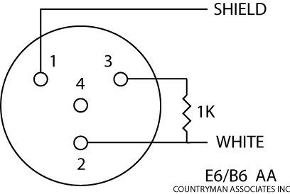
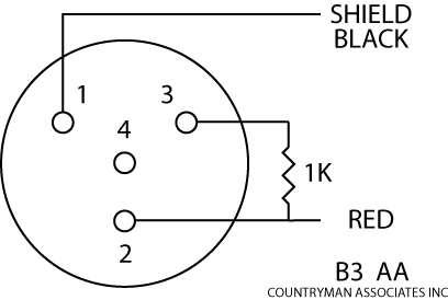
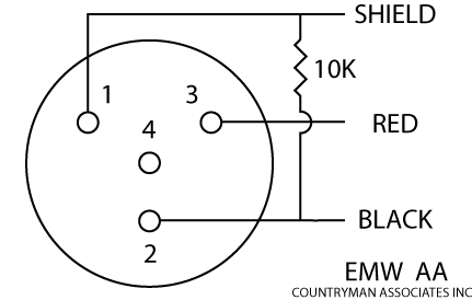
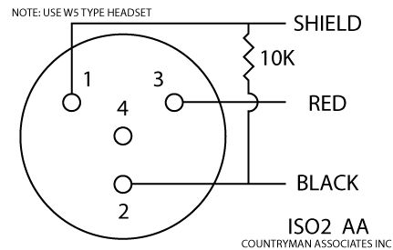
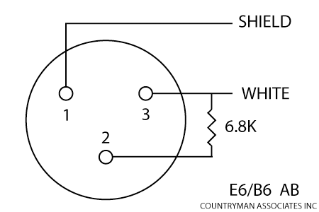
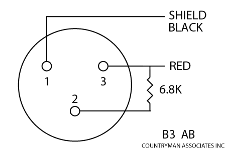
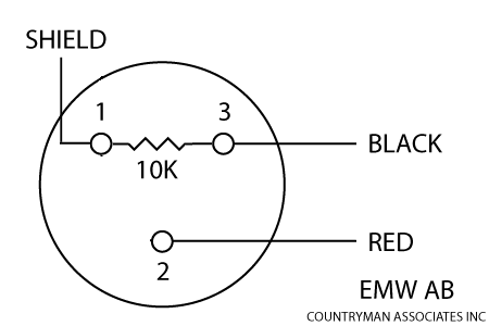
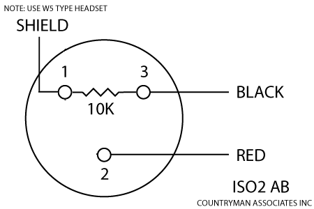
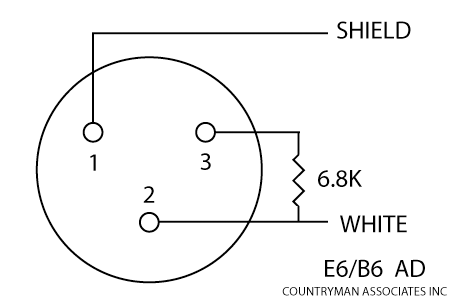
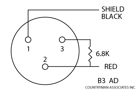
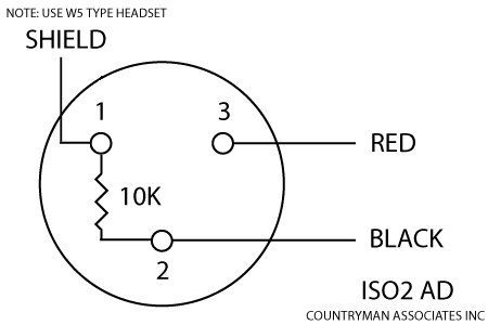
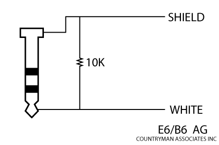
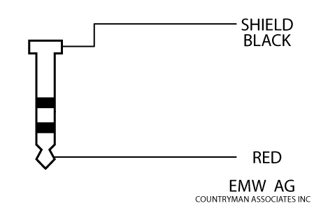
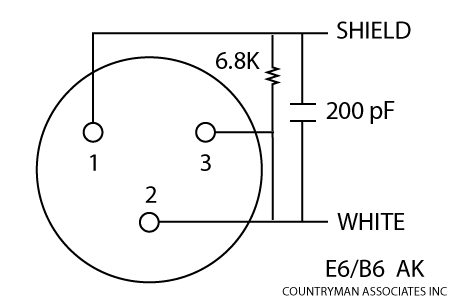
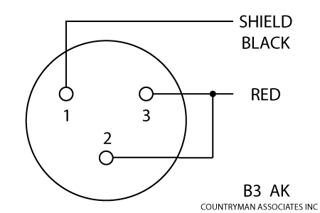
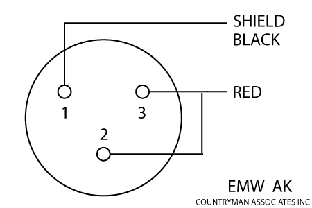
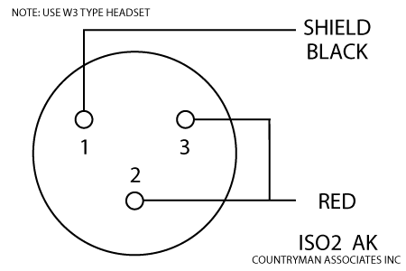
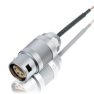
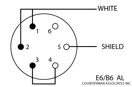
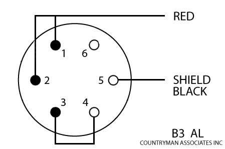
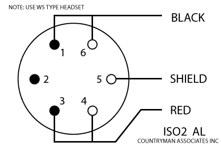
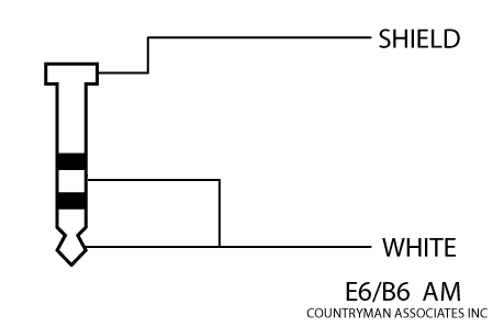
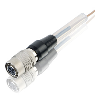
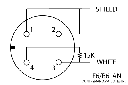
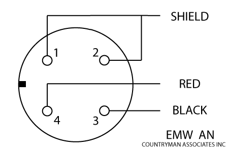
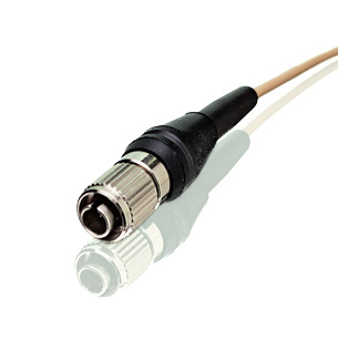
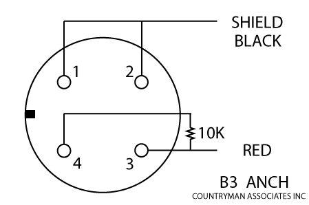
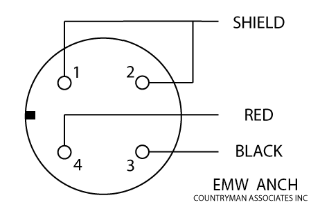
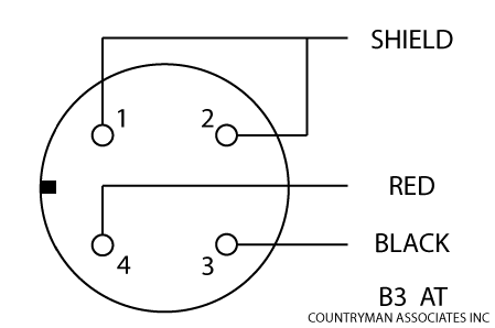
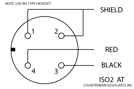
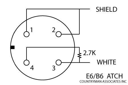
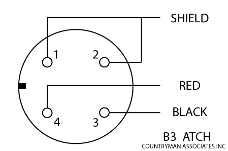
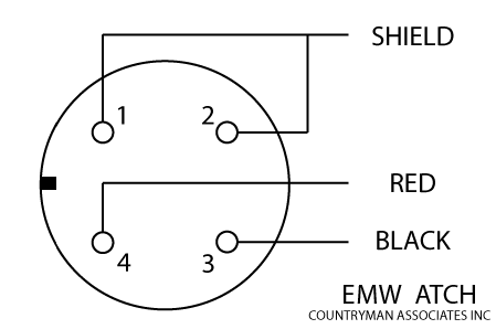
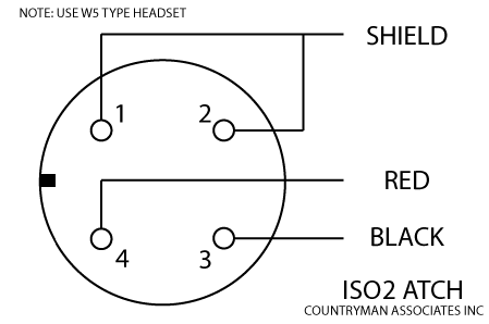
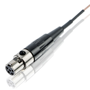
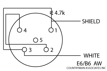
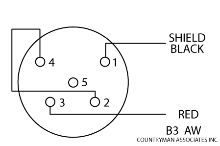
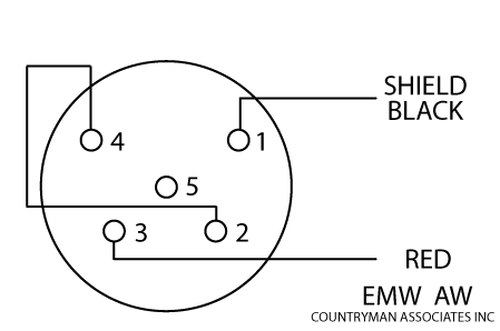
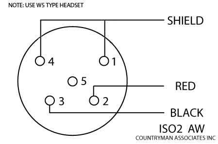
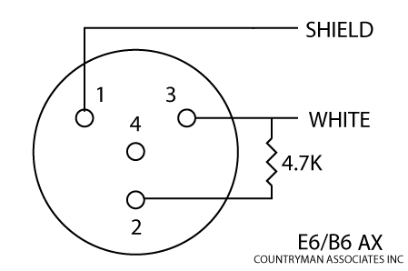
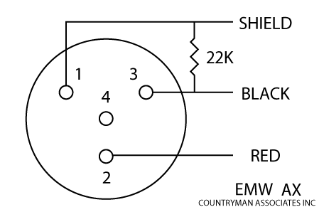
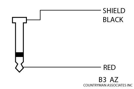
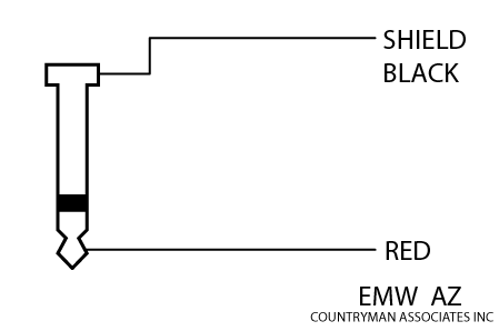
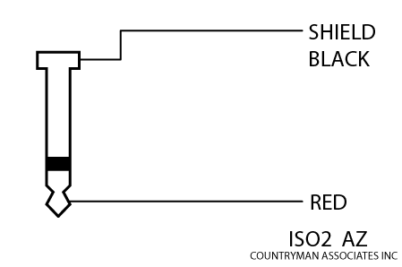
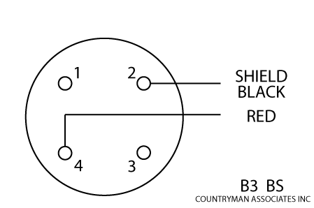
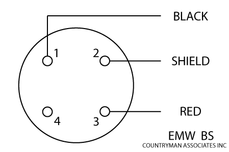
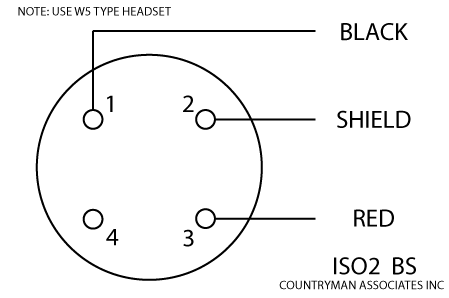
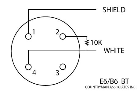
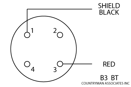
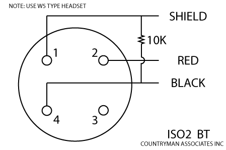
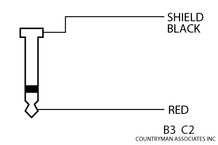
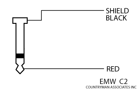
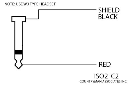
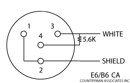
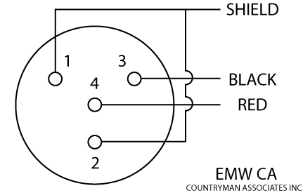
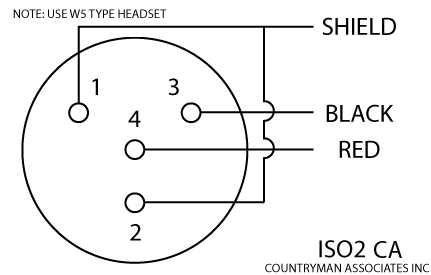
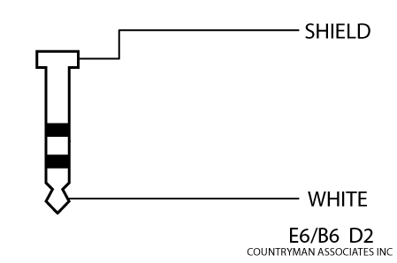
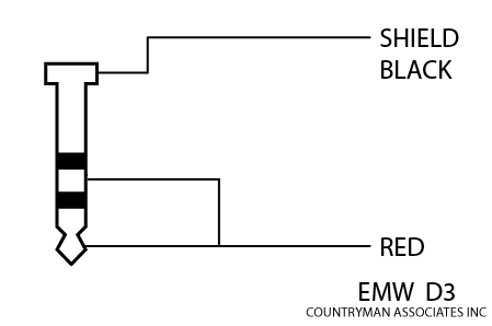
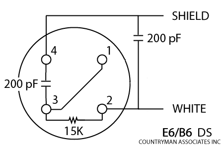
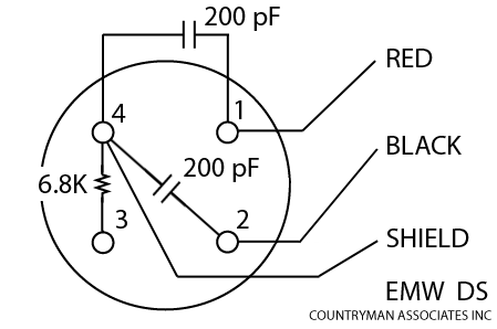
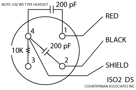
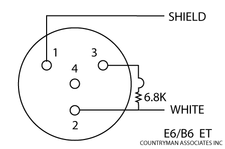
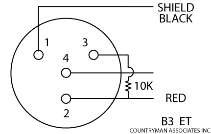
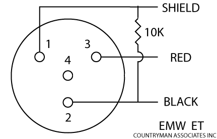
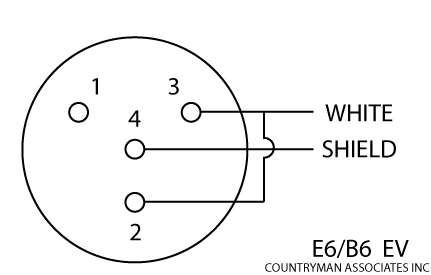
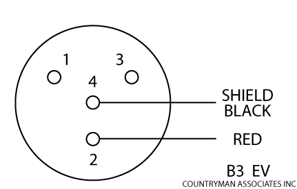
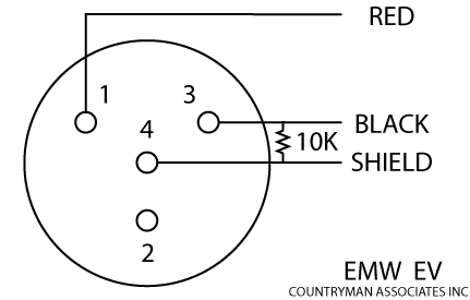
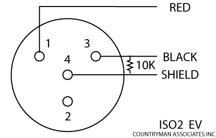
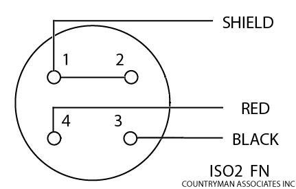
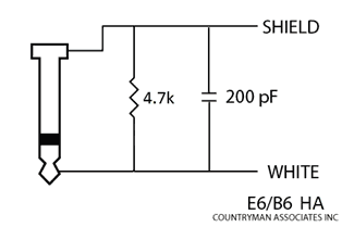
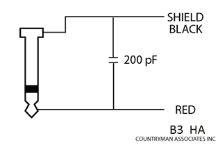
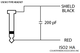
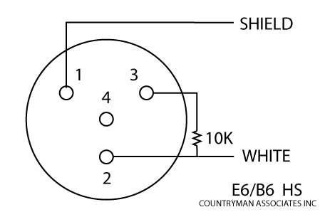
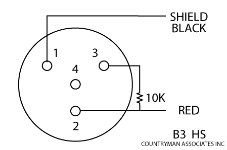
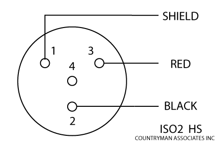
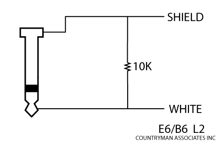
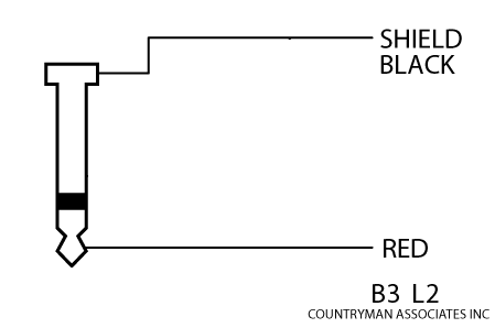
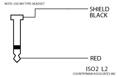
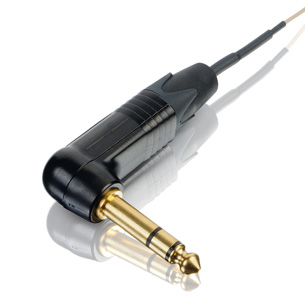
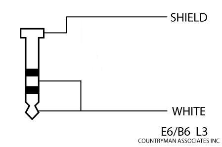
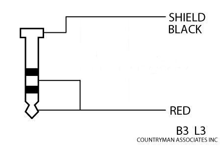
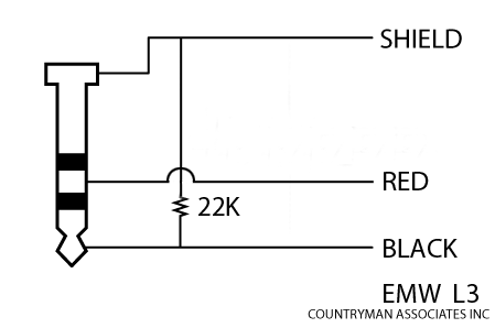
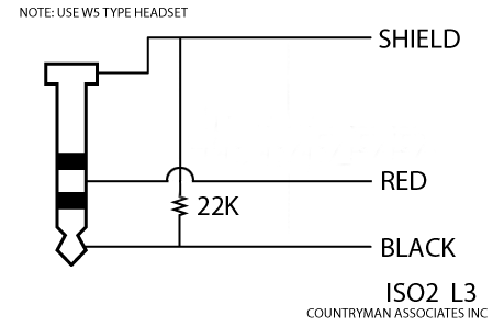
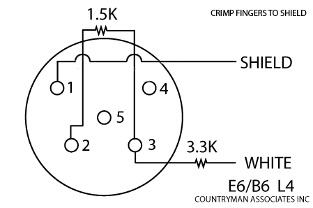
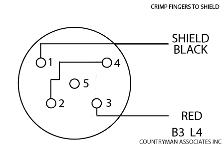
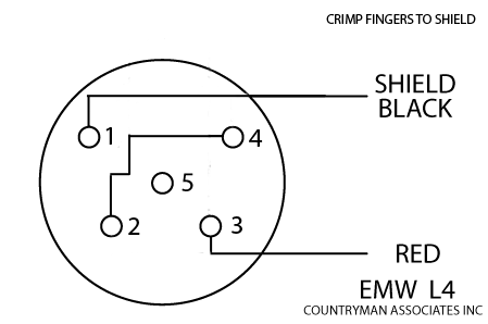
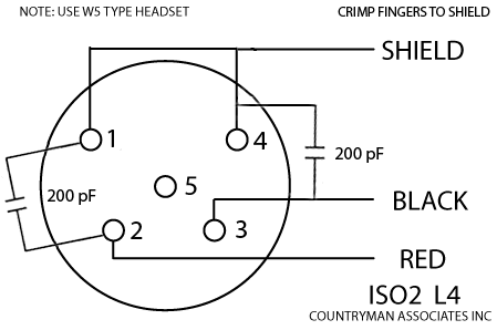
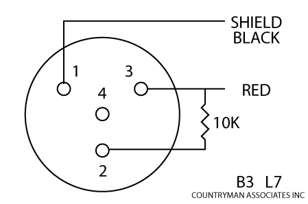
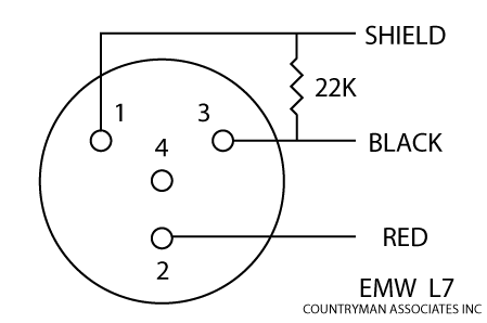
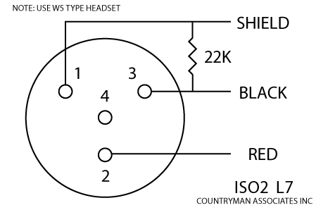
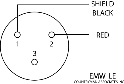
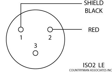
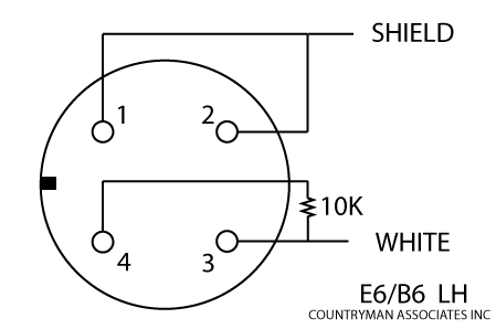
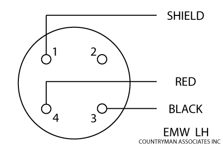
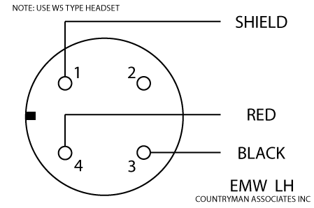
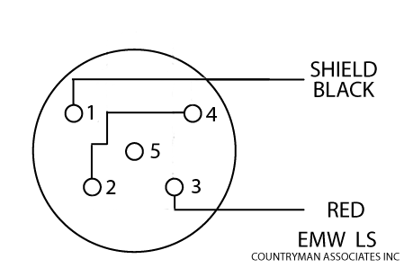
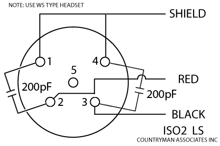
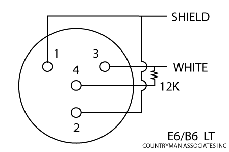
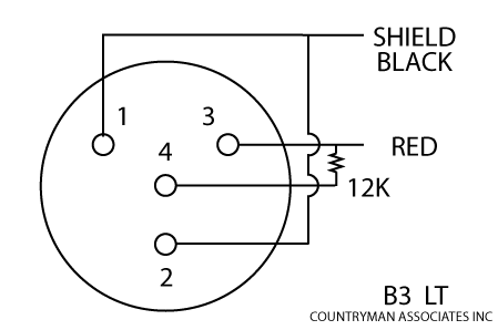
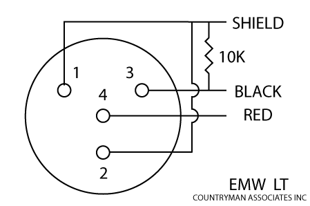
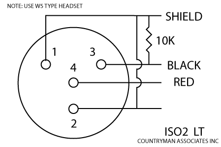
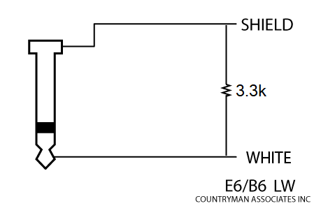
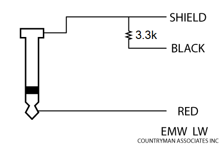
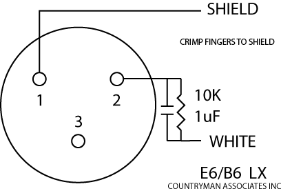
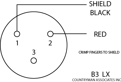
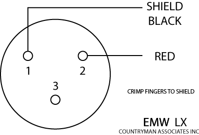
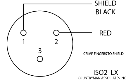
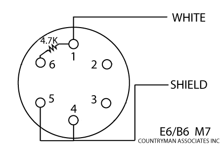
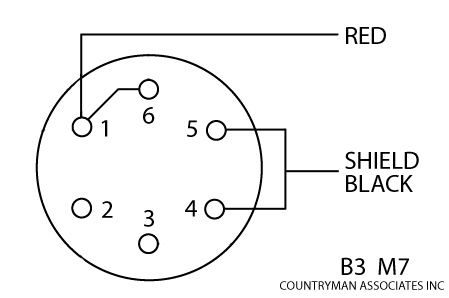
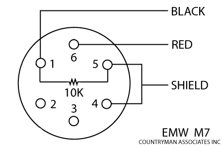
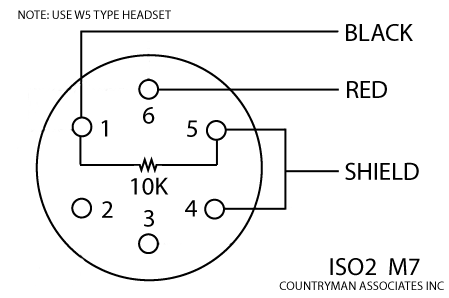
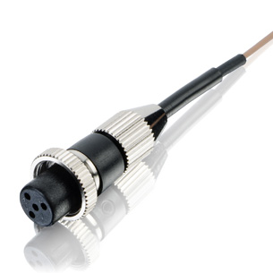
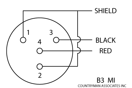
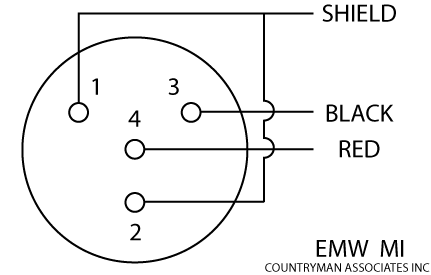
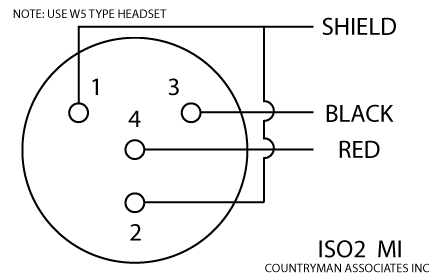
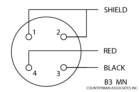
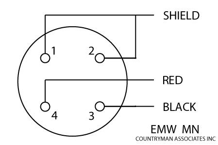
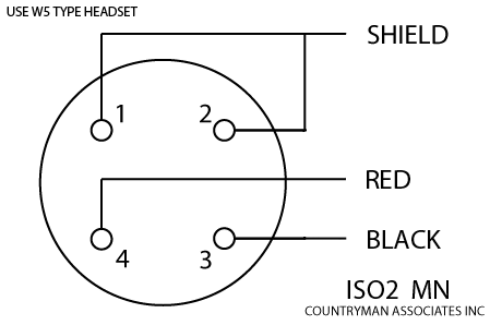
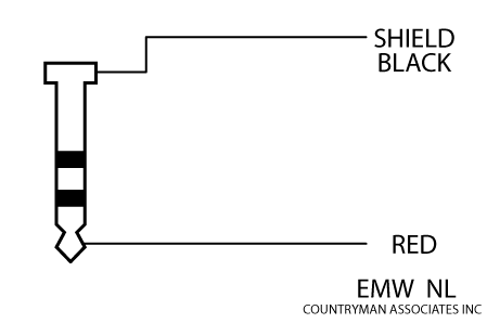
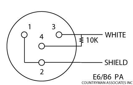
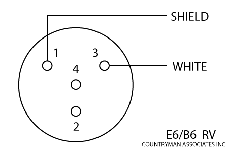
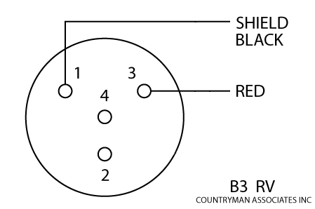
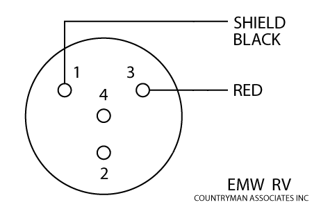
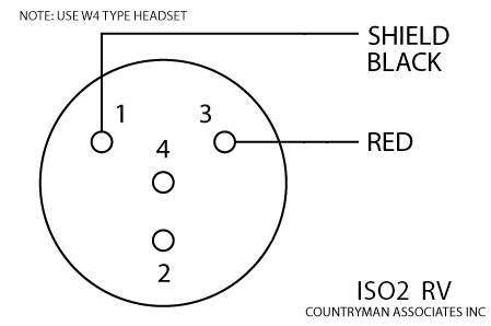
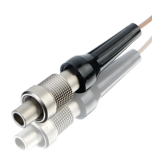
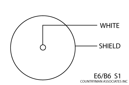
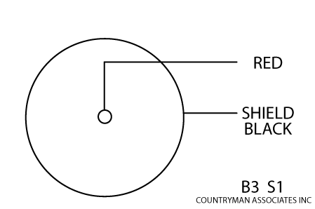
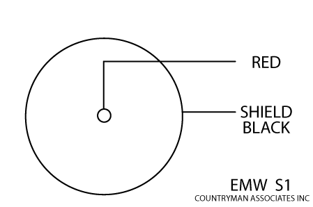
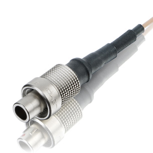
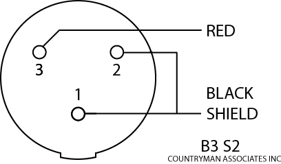
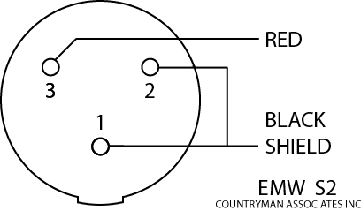
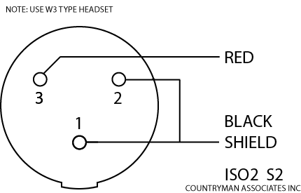
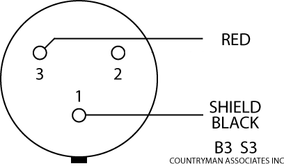
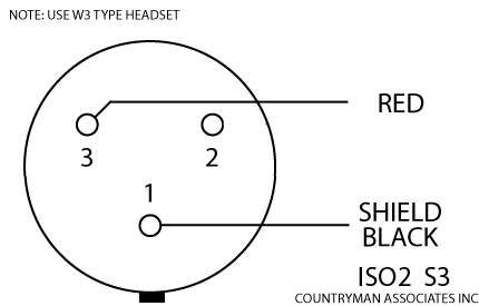
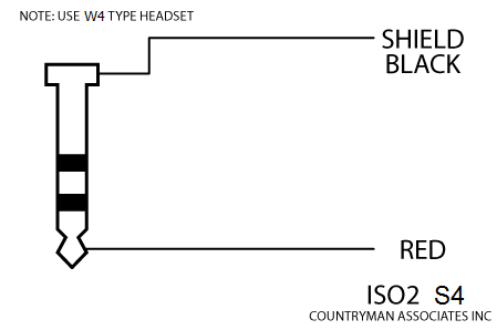
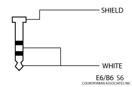
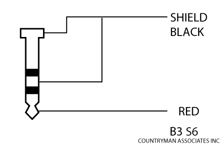
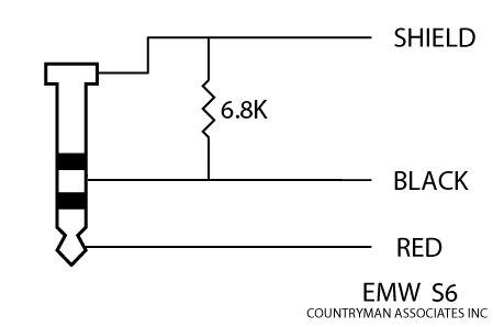
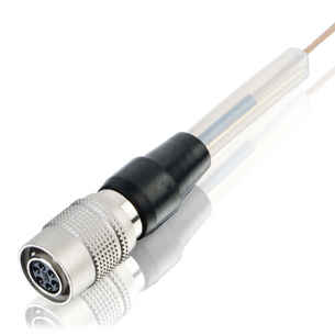
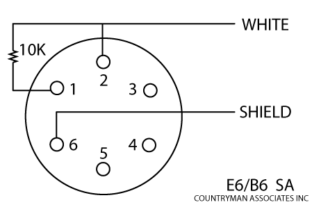
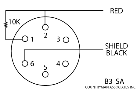
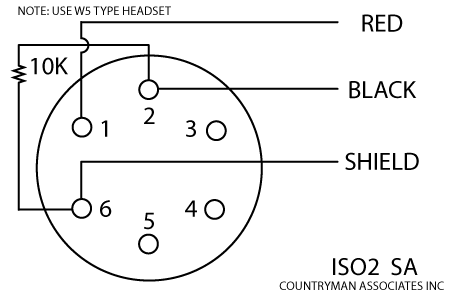
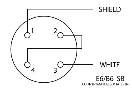
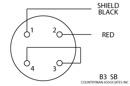
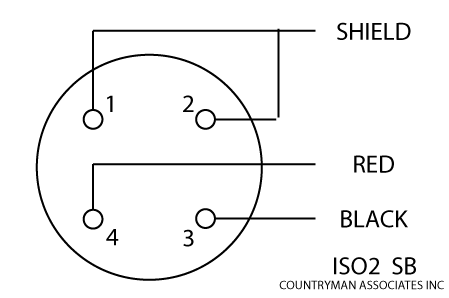
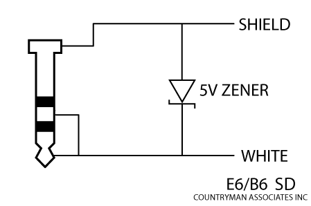
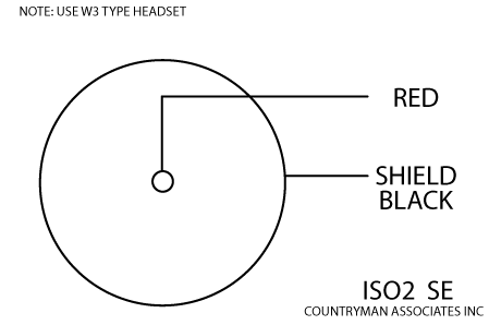
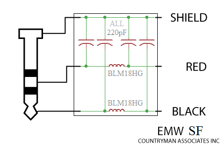
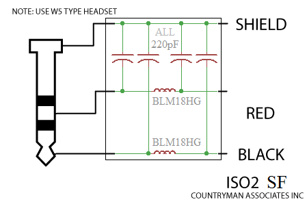
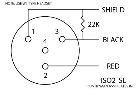
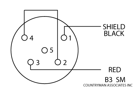
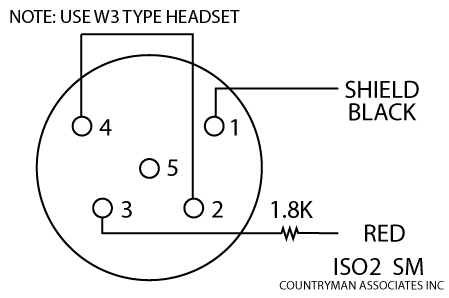
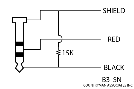
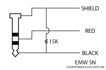
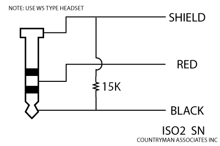
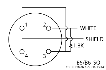
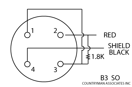
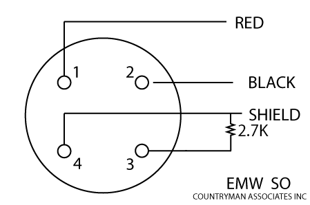
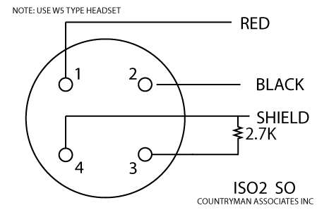
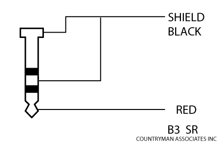
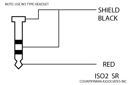
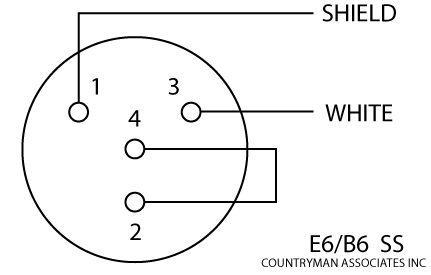
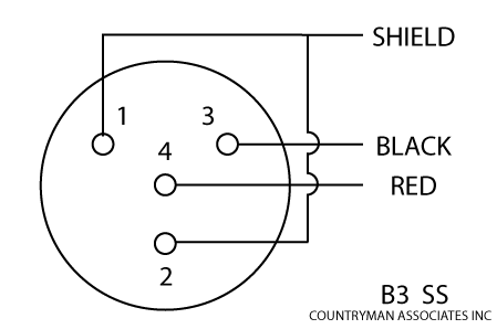
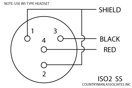
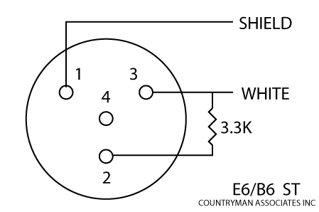
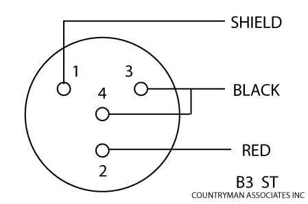
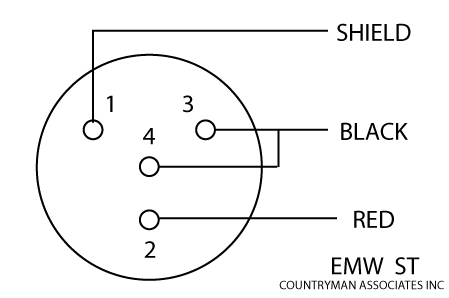
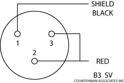
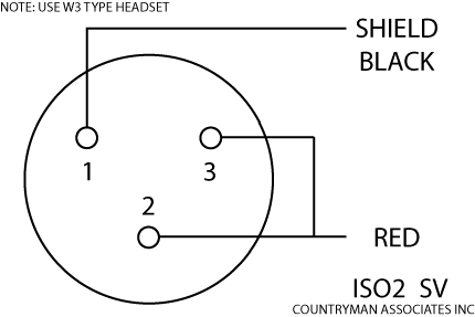
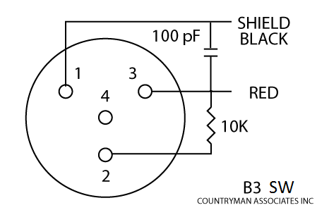
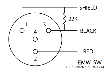
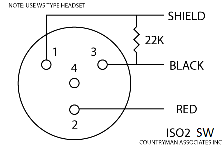
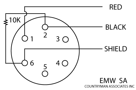
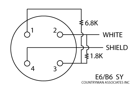
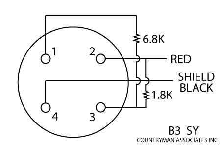
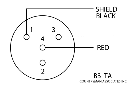
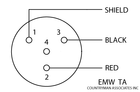
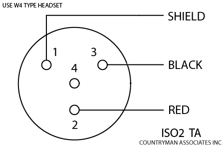
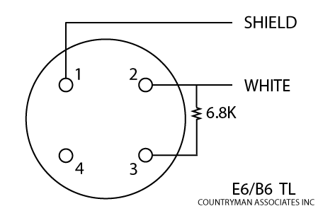
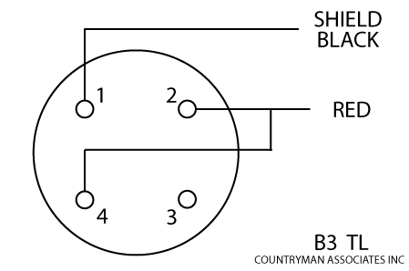
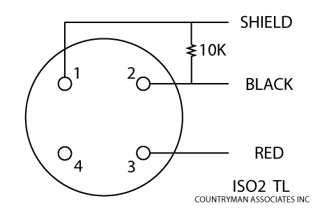
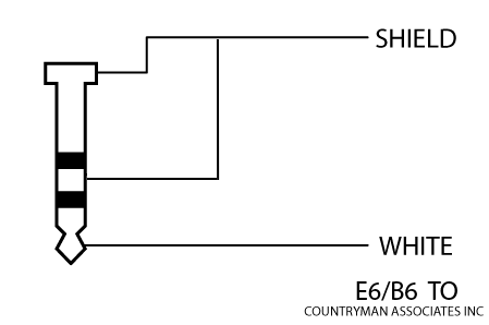
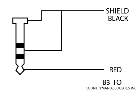
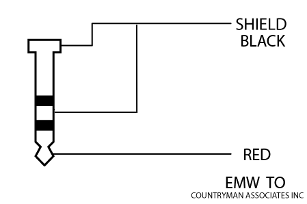
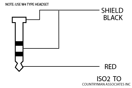
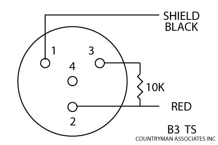
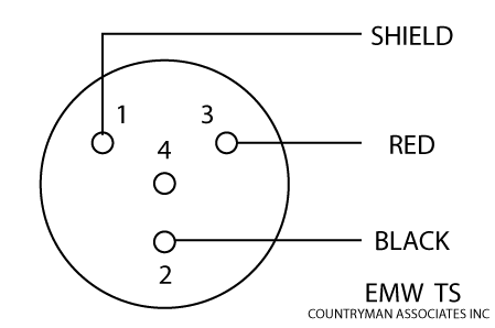
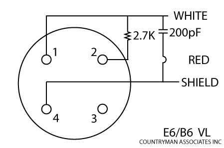
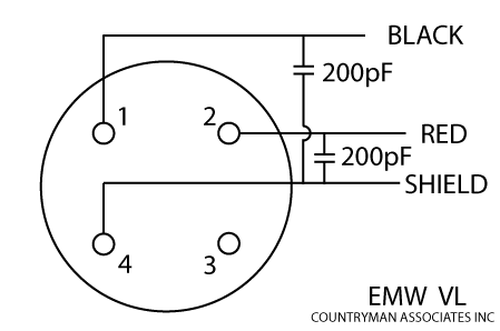
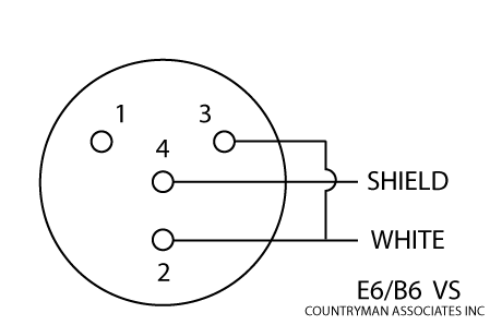
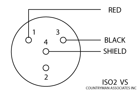
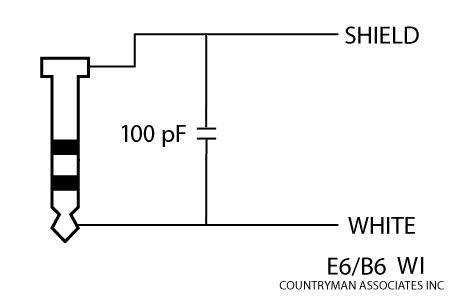
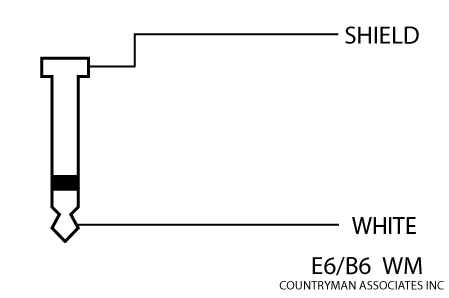
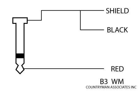
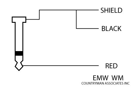
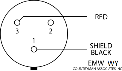
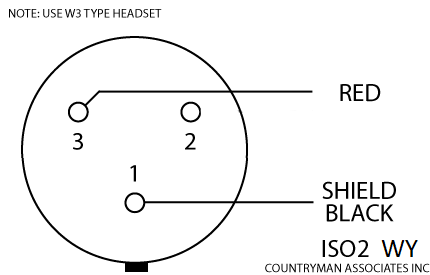
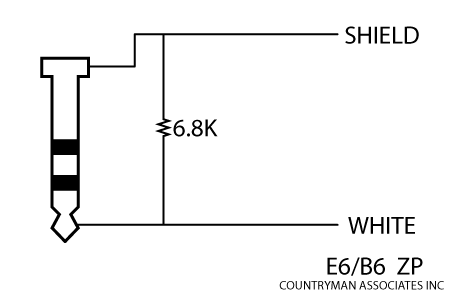
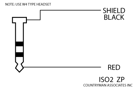
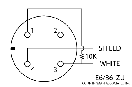
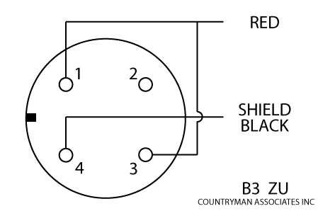
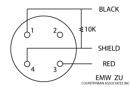
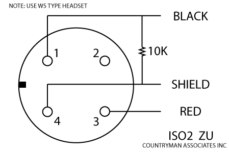
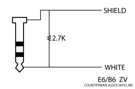
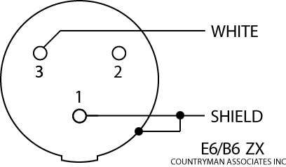
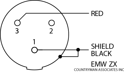
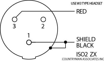